Sine Curve Orderly Tangle

In the 1970s and 1980s Alan Holden described symmetric arrangements of linked polygons which he called regular polylinks or orderly tangle. The fundamental geometric idea of symmetrically rotating and translating the faces of a platonic solid is applicable to both sculpture and puzzles. 

The process started with making a frame out of the geometry; in this case a cube. All 6 faces are moved inwards with the central point of the original cube is used as the origin axis.

Using the same origin, the faces of the geometry are then rotated along their axis at a certain degree to create the orderly tangle.

The faces are then thicken to ensure all of them fixed together.

post_2

Using the method as stated before, an icosahedron is used and different length of movement and degree of rotation is used to suit the shape.

—————————————————————–

Some images can be scanned using augmented reality apps called Augment.

augment-logo-black

Links to Augment apps:

iOS: https://itunes.apple.com/us/app/augment/id506463171

Android: https://play.google.com/store/apps/details?id=com.ar.augment

—————————————————————–

In this experiment, the edges of the icosahedron is replaced with sine curve. 

post_8 post_9

In this experiment, the edges of the icosahedron is replaced with triangular curve.

post_10 post_11

In this experiment, the edges of the icosahedron is replaced with steps curve.

post_12 post_13

——————————————————–

The icosahedron sine curve edges is used to continue with further design. The original sine curve is manipulated using grasshopper to enable the shape to intertwine through itself and interlock without major intersection. This provide more ways to control the curve and makes it easier to assemble. 

A small model is built to see how it holds together.

post_14

post_15post_16

post_17post_18

——————————————————–

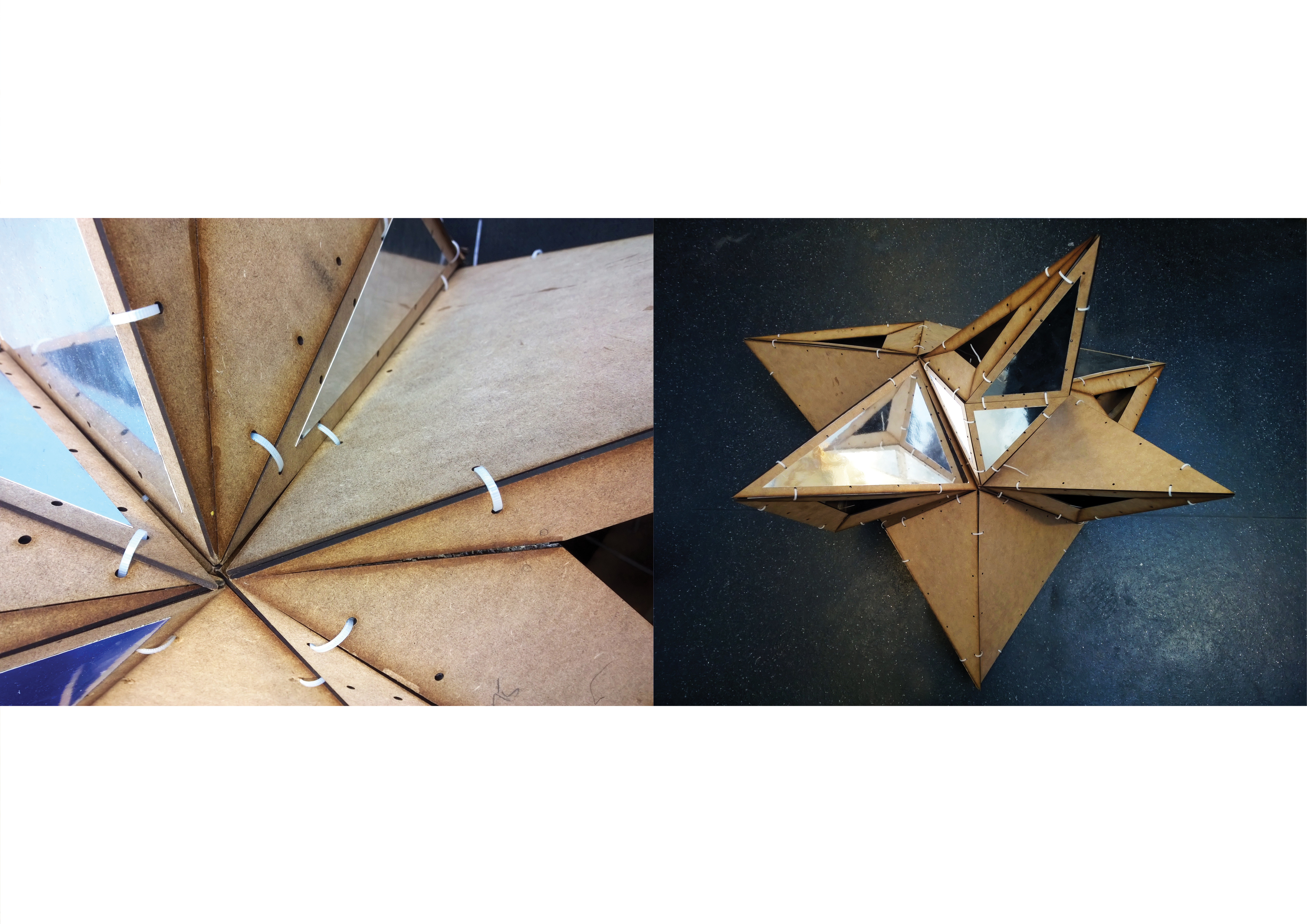
After making the first small scaled model, i started to study on a more efficient jointings needed for the sine curve component as well as the interlocking component needed to connect the face together.

A medium sized model is built with the new jointing design.

 post_19

post_20

 post_21post_22

post_23

——————————————————–

The sine curve polylinks created an icosahedron space on the inside. Each triangle face of the icosahedron corresponds to the sine curve geometry due to the initial process of replacing all the edges with sine curves.

In icosahedron, there is always surface that pairs in a parallel to each other, in this case 10 pairs of the 20 triangle faces. Based on this, i tried to use the surface as a floor plate for the structure. The whole geomtery is rotated so that one of the surface lays flat on the ground. The excess part is then removed.

The section shows the space inside with one of the triangle face acts as a floor plate.

post_24

post_25

—————————- EXPERIMENTS —————————-

Different experiments were carried out using the system as the basis for design. The experiments focus more on a different form other than the spherical nature of the system.

In this experiment, the polylinks is divided into two halves (each half contains 10 modular shape) and the bottom half is move to the side on the x- axis while still intertwine with the top half portion. Due to the adjustment, the bottom half is also slightly moved up on the z-axis to ensure no major intersection. This creates a more elongated structure with the system still intact. The process is repeated with each time the geometry still intertwine between the top and bottom half.The process is then repeated along the y-axis to create a planar design based on the shape.

post_26 post_27

post_28 post_30

——————————————————–

In this experiment, the polylinks is divided into two halves (each half contains 10 modular shape) and the bottom half is removed. The top half contains two component face that is in the same plane but different angle. These two will be used as a sharing planes to array the whole structure. The top half structure is then copied to the adjacent with the parallel face is lined up. The structures will intertwine at the sharing planes helping it to stay in place. The process is repeated with each time the geometry still intertwine at the sharing planes on each iteration.

post_31 post_32

——————————————————–

In this experiment, using one of the component face as a floor plate, the structure is rotated to lay the component face on the floor and all the excess (bottom) are removed. The opposite component face, which is in parallel to the one used as floor plate, will be used as the second floor plate. All the excess (top) are removed as well. The structure is then mirrored along the x and y plane to get a tower shape structure. The trimmed part where the excess are removed will connect with the new mirrored structure making them all connected.

post_34 post_35

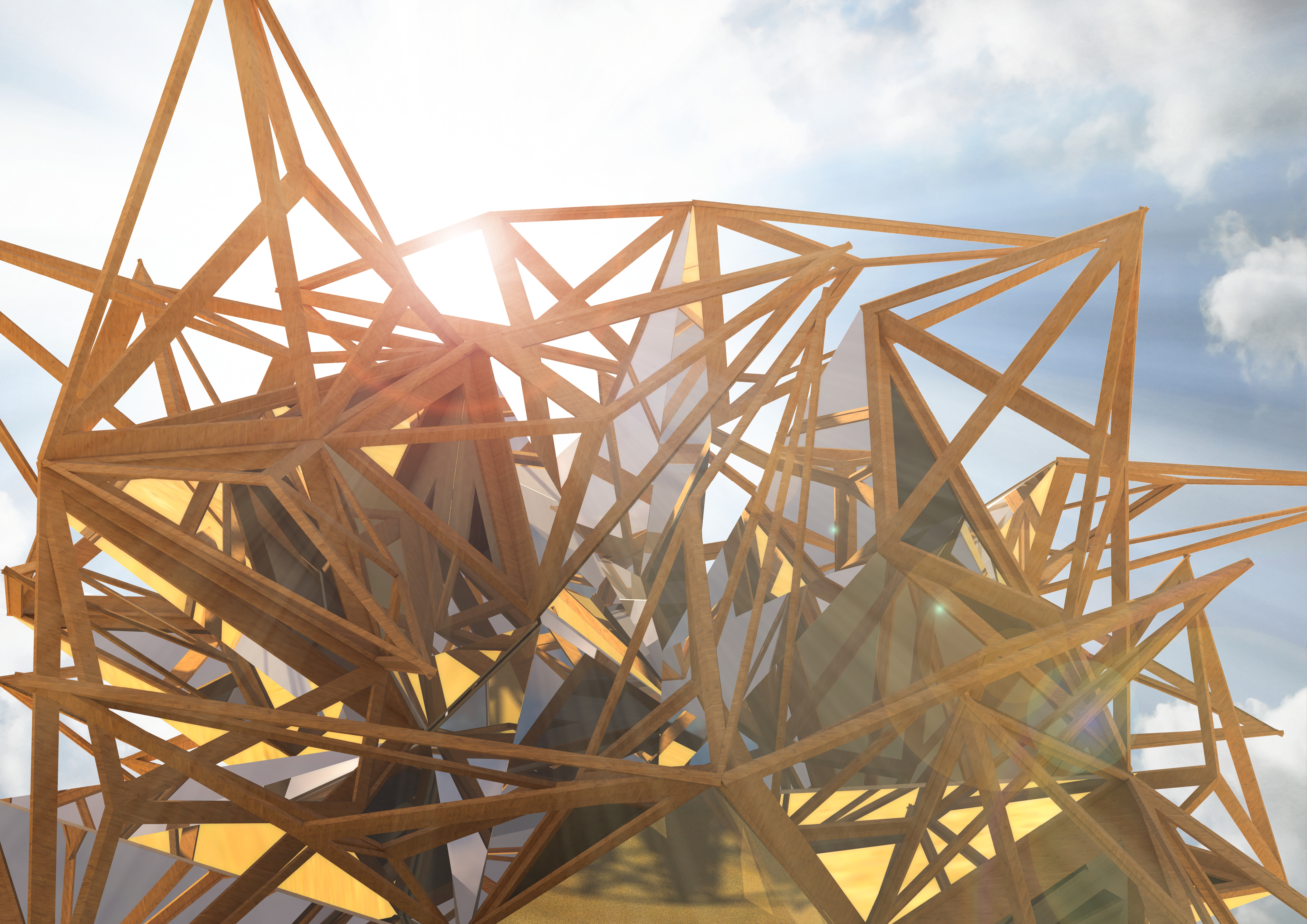
—————————- BURNING MAN PROPOSAL —————————-

Desert Petal

bm03

bm04

bm02

bm01

Exploded and Elevation

Polylinks Catalogue + Augmented Reality

Augmented Reality (AR) is a technology that superimposes a computer-generated image on a user’s view of the real world, thus providing a composite view. For architects and designers, AR enables them to better communicate design intent.  A challenge for architects is that of communicating concepts and visions for buildings.  For many it is difficult to imagine that concept or vision through a floor plan.  The advantage to using augmented reality is in the communication of ideas, concepts and the vision for their building.  This enables all the parties to more quickly reach a full appreciation of the building plan.  When everyone shares a common understanding of the design, the project is executed more efficiently. There are a lot of apps that provides the AR experience and one of them is Augment (http://www.augmentedev.com/).

In my last tutorial, I used Augment to help me create a catalogue of my design which is a system based on regular polylinks. From the system, I have managed to get a lot of different 3D model based on several parameters. Using Augment, I am able to show the 3D model to people just by scanning the embedded image.

1

2

3


The design is based on regular polylinks by sculptor George W. Hart. It is made of a icosahedron with each edges being replaced with different kind of curves. Each face of the icosahedron is then manipulated with different parameters the get different designs. The images below have been embedded with the 3D model where people can scan using the Augment app (link to download is provided at the end) to see the 3D model. The 3D models are limited for now to the ones highlighted with the dashed-line box (click the image, zoom to full size and scan it via Augment). The model can be zoom in by pinching two fingers and rotate by scrolling two fingers in the same direction.

new diagrams2

new diagrams3

new diagrams4

One of the configuration was chosen to be built and further changes to the parameter are done to ensure it will be easier to build. (click image and scan)AR2AR3

Further improvement and more 3D models are being made and will be included into the catalogue in the future.

Links to Augment apps:

iOS: https://itunes.apple.com/us/app/augment/id506463171

Android: https://play.google.com/store/apps/details?id=com.ar.augment

(X)-Cursive

title 1 copy

export 16

(X)-cursive stands for explosive recursive polygons which is inspired by the recursive mountain fractals system introduced by Alain Fournier. The (X)-cursive structure is a transformation of glass to wood through iterations and will be a beautiful and exciting structure for people to climb and play with. The different densities of the structure will provide a beautiful shadows during the day. The mirrors which are parts of the structure will produce an infinite recursion through reflections which makes this structure looks like a desert sculpture.

export 1

The principle of the subdivision method is to recursively subdivide (split) polygons of a model up to a required level of detail. At the same time the parts of the split polygons will be perturbed. The initial shape of the model is retained to an extent, depending on the perturbations. Thus, a central point of the fractal subdivision algorithm is perturbation as a function of the subdivision level. Concerning mountains, the higher the level the smaller the perturbation, otherwise the mountains would get higher and higher. In addition there must be a random number generator to obtain irregularities within the shape – and to achieve a kind of statistical similarity:

 P_n = p( n ) * rnd();

 Where p_n = perturbation at level n,

P( ) = perturbation function depending on level n, and

Rnd( ) = random number generator.

 Fournier developed a subdivision algorithm for a triangle. Here, the midpoints of each side of the triangle are connected, creating four new subtriangles.

For the perturbation of these points, they use the self-similarity and conditional expectation properties of fractional brownian motion.it2

The (X)-Cursive will use plywood as its main material, with mirror sheets as the secondary material. The plywood are cut according to the design before being assemble using zip ties. The overall dimension is big to provide enough space for people to crawl inside the structure. The lower part of the structure is attached to a base plate using hinges in order to ensure stability for the whole structure.

 export 14export 13

export 15

Proportion and Interaction

export 19

export 17

Mesh Recursive Subdivision based on Alain Fournier’s algorithm

The principle of the subdivision method to generate mountains is to recursively subdivide (split) polygons of a model up to a required level of detail. At the same time the parts of the split polygons will be perturbed. The initial shape of the model is retained to an extent, depending on the perturbations. Thus, a central point of the fractal subdivision algorithm is perturbation as a function of the subdivision level.

Concerning mountains, the higher the level the smaller the perturbation, otherwise the mountains would get higher and higher. In addition there must be a random number generator to obtain irregularities within the shape – and to achieve a kind of statistical similarity:

P_n = p( n ) * rnd();

Where p_n = perturbation at level n,
P( ) = perturbation function depending on level n, and
Rnd( ) = random number generator.

Fournier developed a subdivision algorithm for a triangle. Here, the midpoints of each side of the triangle are connected, creating four new sub triangles.

Based on this algorithm, the process is done recursively to all the new triangles generated so that the shape is not limited to vertical mountains.

final

final2

 final3

Random perturbation is where the first iteration is based on a random parameter within the range of 0-9 and the following iterations also are based on a random parameter. This is done using grasshopper by setting the seed number of the initial polygon and the seed number of the iterations. All iterations perturbed based on the z-axis of the new polygon produced.

This resulted in a different shape of the ‘base’ and all the iterations after the first one, ranging from small to big volume depending on the seed of the random number generated. By producing polygons using random perturbation, each iteration is different than the others. The iteration runs for ten (10) times using grasshopper.

Base perturbation * random seed: 1 – 10

Second – third perturbation * random seed: 0 – 10

final11final12final13

final14final15

Based on the principle, one module is chose to continue with the next step. The module chosen is the 5;5 module which is Base perturbation * random seed: 5 and Second – third perturbation * random seed: 5. After the second iteration, whenever there are surfaces which will intersect, one or both of the surface is removed. This resulted in a random yet in control structure based on the principle applied.

final17

final18

EXTRA

EXTRA2

WP_20141106_02_09_48_Raw copy

For the next brief, I am developing the module to grow further than the third iteration and grows following a certain flow.