Growth From The Ger

Introduction

‘Growth From The Ger’ seeks to analyse the vernacular structure of the traditional nomad home and use parametric thinking to create a deployable structure that can grow by modular.

‘Ger’ meaning ‘home’ is a Mongolian word which describes the portable dwelling. Commonly known as a ‘yurt’, a Turkish word, the yurt offered a sustainable lifestyle for the nomadic tribes of the steppes of Central Asia. It allowed nomads to migrate seasonally, catering to their livestock, water access and in relation to the status of wars/conflicts. An ancient structure, it has developed in material and joinery, however the concept prominently remaining the same.

Inspiration

Growing up in London, I fell in love with the transportable home when I first visited Mongolia at the age of 17. The symmetrical framework and circulating walls create a calm and peaceful environment. In the winter it keeps the cold out and in the summer keeps the heat out. The traditional understanding of placement and ways of living within it, which seems similar to a place of worship, builds upon the concept of respect towards life and its offerings.

Understanding the beauty of the lifestyle, I also understand the struggles that come with it and with these in mind, I wanted to explore ways of solving it whilst keeping the positives of the lifestyle it offers.

Pros: Deployable, transportable, timber, vernacular, can be assembled and dissembled by one family, can vary in size/easily scaleable depending on user, low maintenance, sustainable, autonomous.

Cons: Difficult to sustain singularly, not water proof, no privacy, no separation of space, low ceiling height, can’t attach gers together, low levels of security.

A digital render produced on Rhino, showing the steps of building a ger in elevation.

Lattice Analysis and Testing

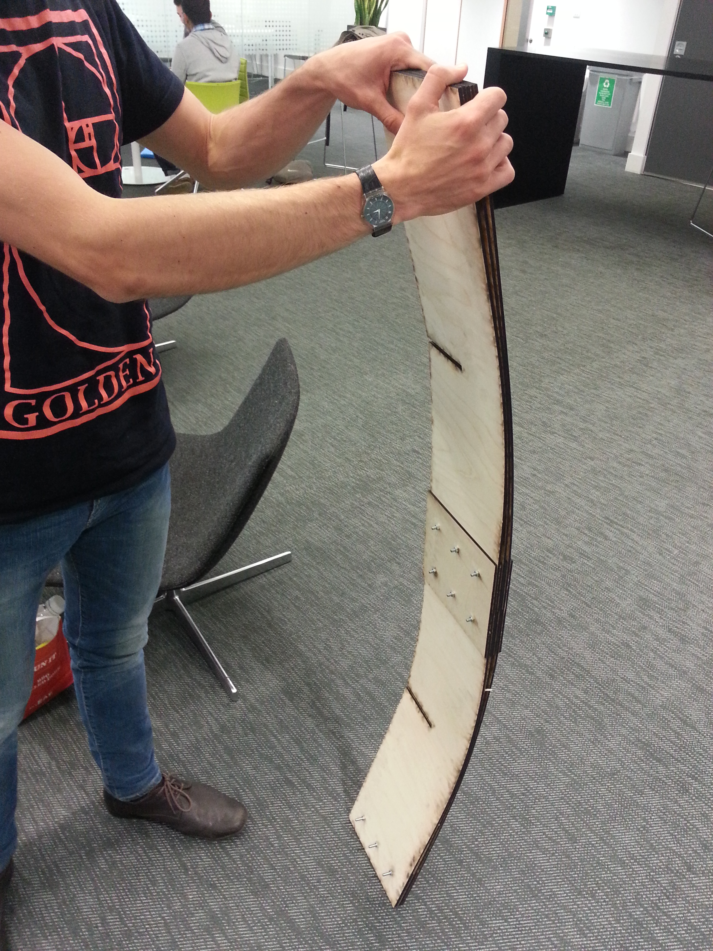
To understand the possibilities of the lattice wall, I created a 1:20 plywood model using 1mm fishing wire as the joinery. This created various circular spirals and curves. The loose fit of the wire within the holes of timber pieces allowed such curves to happen and created an expanding body. The expansion and flexible joinery allows it to cover a wider space in relation to the amount of material used.

A series of photos showing the expansion and various curves of the lattice model.

I created the same latticework at 1:2 scale to see if the same curvature was created.

1:2 plywood model testing flexible joinery and curvature at large scale.

Locking the curve to create a habitable space. I did this by changing the types of joints in different parts of the structure.

A series of images showing the deployment of the structure and locked into place.

To create a smoother and more beautiful curve I change the baton to a dowel and densify the structure.

Model photo of curve in full expansion.

To lock the lattice curve in expansion I extrude legs that meet the ground and tie together.

Model photo of curve in full expansion and locked in place.

Manufacturing and assembly

Diagram of the construction sequence of model.
A series of photos showing 1:2 scale model being deployed.
1:2 prototype made from 18mmx18mm square plywood sticks joined together by twine.

The model made from sheet plywood cost approximately £30 and took one working day to make for one person. However, a more sustainable material and process needed to be considered as the process of making plywood contradicted this.

Photo showing the modular growth of the module. Models made from 18x18mm square sticks of softwood timber and joined together with twine.

This model can be made by one person with the use of a wood workshop. The timber pieces were bought at 18mm x 95mm x 4200mm, 13 pieces of these were enough to make three modules, roughly costing £170 in total. Each module takes approximately 5 hours to construct, this involves the tying of the measured length twine joints. The structure is lightweight and each module is easily transportable by one person.

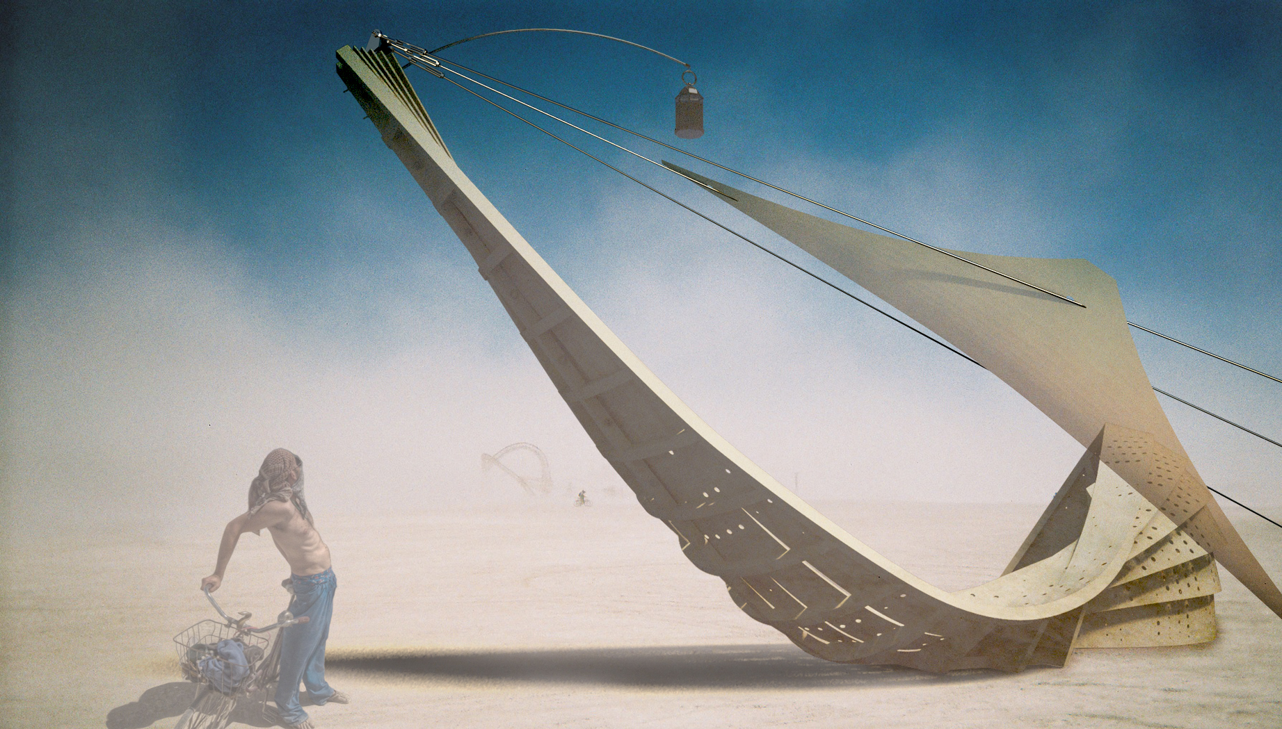
Growth from the ger: modular growth

Digital render of modules arrayed together at angles, produced on Grasshopper and Rhino.
Perspective view.
Digital render of modules arrayed together at angles, produced on Grasshopper and Rhino.
Perspective view.
Digital render of modules arrayed together at angles, produced on Grasshopper and Rhino.
Plan view.
Digital render of modules arrayed together at angles, produced on Grasshopper and Rhino.
Diagram showing the plan functions of each space and modules.

Burning Man Festival | Bismuth Bivouac

Help us reach our Kickstarter target! http://kck.st/1ESCVFb

Inspired by the geometry from the crystalline growth pattern of the element Bismuth (Bi), the Bismuth Bivouac is a playful pavilion that celebrates the orthogonal geometries that can exist in natural Bismuth crystals to form an intriguing cubic structure, with spiralling disruptions on each face that are governed by the golden ratio. From a distance, the structure appears as a seemingly solid cube, but upon closer inspection, the internal spaces can be explored and utilised.The beautiful iridescent colours of crystal are to be translated into the proposal through coloured LED strip lighting, built into the simple dimensional lumber structure of the pavilion, so at night the Bismuth Bivouac gives has the same visually mesmerizing, colourful effect of the bismuth crystals in nature. The project aims to play with the participants perception of depth and scale in this mirroring structure – from afar, the structure will appear as a dense cube that sits on the playa, but as the participants move towards the structure, they will begin to be able to see through parts of the structure due to the stepped nature of the geometry and holes formed from spiral disruptions. The structure provides sheltered from harsh desert sun, but also provides a plaything for the sun to casts its shadows during the day, and for people to cast their own shadows with their own illuminations at night.

Development

bismithbiv_Page_01

Construction

 bismithbiv_Page_03

bismithbiv_Page_04

bismithbiv_Page_06

bismithbiv_Page_05

Visualizations

 bismithbiv_Page_07

bismithbiv_Page_08

bismithbiv_Page_09

bismithbiv_Page_10

Miura Ori based curved surface origami structures

I have been researching Miura pattern origami as a structural solution for rapidly deployable structures. Miura ori are interesting as structures due to their ability to develop from a flat surface to a 3D form, and become fully rigid, with no degrees of freedom, once constrained at certain points. 141110_Year 2 working folio2 Physical and digital experiments with Miura Ori have taught me that certain topographies can be generated by developing a modified Miura pattern. With the help of Tomohiro Tachi’s excellent research on the subject of curved Miura ori, including his Freeform Origami simulator (http://www.tsg.ne.jp/TT/index.html) I have learned that Miura ori surfaces that curve in the X and Y axes can be generated by modifying the tessellating components, however these modifications require some flexibility in the material, or looseness of the hinges. 141110_Year 2 working folio6 As a system for a rapidly deployable structure, I am most interested in the potential for the modified Miura ori to work as a structure built with cheap, readily available sheet materials which are generally planar, so I will continue to develop this system as a rigid panel system with loose hinges that can be tightened after the structure is deployed. 141110_Year 2 working folio4 In order to test the crease pattern’s ability to form a curved surface, I have defined a component within the Miura pattern that can tessellate with itself. The radius of this component’s developed surface is measured as it is gradually altered.

With the objective being to develop a system for the construction of a rapidly deployable structure, I have also been interested in understanding the Miura ori’s characteristics as it is developed from flat. Physical and digital tests were performed to determine the system’s willingness to take on a curve as its crease angles decrease from flat sheet to fully developed. I found the tightest radius was achieved rapidly as the sheet was folded, with the radius angle reaching a plateau. This is interesting from the perspective of one with the desire to create a structure that has a predictable surface topography, as well as from a material optimisation standpoint; the target topography can be achieved without the wasteful deep creases of an almost fully developed Miura ori. 141110_Year 2 working folio5 With the learnings of the modified Miura ori tests in mind, a simple loose hinged cylinder is simulated. As the pattern returns on itself and is fastened, the degrees of freedom are removed and the structure is fully rigid. 141110_Year 2 working folio A physical model of the system was constructed with rigidly planar MDF panels and fabric hinges. The hinges were flexible enough to allow the hinge movement necessary in developing this particular modified Miura ori, however some of the panels’ corners peeled away from the fabric backing as the system was developed from flat. A subsequent test will seek to refine this hinge detail, with a view to creating a scalable construction detail that will allow sufficient flexibility during folding, as well as strength once in final position. 141110_Year 2 working folio3

John Konings

j.e.konings@gmail.com

Thursday 12th December 2013

We just finished our last tutorials of the first term! Congratulations to all the students for the great three months and looking forward to the remaining two terms.

Students completed both briefs (brief01:systems and brief2A:festival) and are starting the case studies of events as part of our last brief (brief2B:realise).

Here are couple pictures of the projects we have seen during the last tutorials. Where do you suggest building the structures over the summer?

Merry Christmas & best wishes for the New Year!!

John Konings's towering gridshell.
John Konings’s towering gridshell.

John Konings's towering gridshell.
John Konings’s towering gridshell.

John Konings's towering gridshell.
John Konings’s towering gridshell.

Andres Jippa's 3D prints, driven by Chaos theory's strange attractors.
Andres Jippa’s 3D prints, driven by Chaos theory’s strange attractors.

Andres Jippa's 3D prints, driven by Chaos theory's strange attractors.
Andres Jippa’s 3D prints, driven by Chaos theory’s strange attractors.

Andres Jippa's 3D prints, driven by Chaos theory's strange attractors.
Andres Jippa’s 3D prints, driven by Chaos theory’s strange attractors.

Andres Jippa's 3D prints, driven by Chaos theory's strange attractors.
Andres Jippa’s 3D prints, driven by Chaos theory’s strange attractors.

Andres Jippa's 3D prints, driven by Chaos theory's strange attractors.
Andres Jippa’s 3D prints, driven by Chaos theory’s strange attractors.

Andres Jippa's 3D prints, driven by Chaos theory's strange attractors. Construction Component.
Andres Jippa’s 3D prints, driven by Chaos theory’s strange attractors. Construction Component.

Henry Turner's Curved Intersecting Plywood Wave Structure
Henry Turner’s Curved Intersecting Plywood Wave Structure

Ieva Ciocyte's Flame Tower made of Intersecting plywood components
Ieva Ciocyte’s Flame Tower made of Intersecting plywood components

Sarah Shuttleworth's Moebius Strips made of Steel Stars.
Sarah Shuttleworth’s Moebius Strips made of Steel Stars.

William Garforth-Bless' Bamboo Hammock Amphitheatre
William Garforth-Bless’ Bamboo Hammock Amphitheatre

William Garforth-Bless' Bamboo Hammock Amphitheatre
William Garforth-Bless’ Bamboo Hammock Amphitheatre

Updates 2 on Shipwreck

We are now on Kickstarter! Click on the image below or on this LINK to kindly back our projects.

Swing-Kickstarter-logo

Little summary of our productive day at Westminster with Chris Ingram and Georgia Collard-Watson: We produced a 1:1 physical model of the wood laminate technique recommended by Ramboll (drawing shown in previous post). We will us this technique to form the twisting longitudinal spines on our building.

The openings on the back ribs are now defined parametrically by a sine curve and unroll with the strips for fabrication.We tested couple options and are happy with the one shown below which breaks the direction of the strips.

Working on the parametric model with Chris Ingram at Westminster University

Georgia Collard-Watson with the 1:1 laminate prototype

Chris Ingram testing the bendiness of the laminate structure

Testing the notches
Testing the notches

Resolving Shipwreck's structure - Working on the interface between back stripes and vertical ribs.
Resolving Shipwreck’s structure – Working on the interface between back stripes and vertical ribs.

Resolving Shipwreck's structure - Working on the interface between back stripes and vertical ribs.
Resolving Shipwreck’s structure – Working on the interface between back stripes and vertical ribs.

Modelling the ribs and notches - We are currently adapting the ribs and spine to add strength.
Modelling the ribs and notches – We are currently adapting the ribs and spine to add strength.

The Sine curve Interface controlling the back strips openings on Grasshopper

The back strips openings

Burning Man Art Grants

Toby and I are very very happy to announce that DS10 has won the Burning Man Art Grant twice with Georgia Rose-Collard’s project Shipwreck and Thanasis Korras’ Fractal Cult.

DS10 get ready, we are going to Nevada this summer!!!

burning man IKONOS
Burning Man Festival Satellite Image

Georgia Rose-Collard's Shipwreck
Georgia Rose-Collard’s Shipwreck

Thanasis Korras' Fractal Cult
Thanasis Korras’ Fractal Cult

We have recorded a joyful song for the occasion 😉 Yooohoooo

A Week at Grymsdyke Farm

We just finished our week at Grymsdyke Farm, Buckinghamshire. Ten students spent about two nights each working on their individual projects, building a 1:1 to 1:5 prototype using the available technology: a CNC Milling Machine (with RhinoCam), a laser cutter, a Z-Corp and a RepRap 3Dprinter.

DS10 would like to thank Guan Lee, Ed Grainge and Kate for their precious help and patience on the CNC, Jessie Lee and Keith McDonald for their great advices!

Below are some pictures of the week.

121213_Farm_71Above: Dhiren Patel’s “Ear Parabola” being assembled

121213_Farm_59Above: Dan Dodds testing the fiber optic cables of his Sectionned Harmonograph

121213_Farm_115Above: Emma Whitehead cutting her convection cell models out of plywood

121213_Farm_123Above: Thanasis Korras’ CNC milled components for his giant fractal building.