Through extensive research into the construction of grid shells, as well as differential geometry, I present a design solution for a complex grid structure inspired by the highly symmetrical and optimised physical properties of a triply periodic minimal surface. The proposal implements the asymptotic design method of Eike Schling and his team at Technical University of Munich.
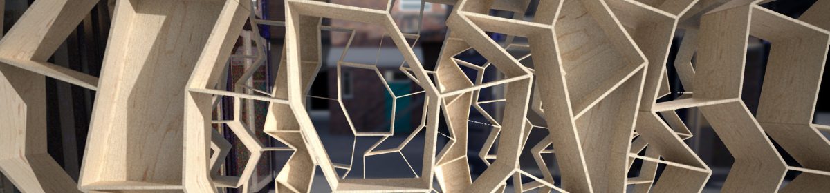
‘Minimal Matters’ utilises the several geometric benefits of an asymptotic curve network to optimise cost and fabrication. From differential geometry, it is determined asymptotic curves are not curved in the surface normal direction. As opposed to traditional gridshells, this means they can be formed from straight, planar strips perpendicular to the surface. In combination with 90° intersections that appear on all minimal surfaces (soap films) this method offers a simple and affordable construction method. Asymptotic curves have a vanishing normal curvature, and thus only exist on anticlastic surface-regions.
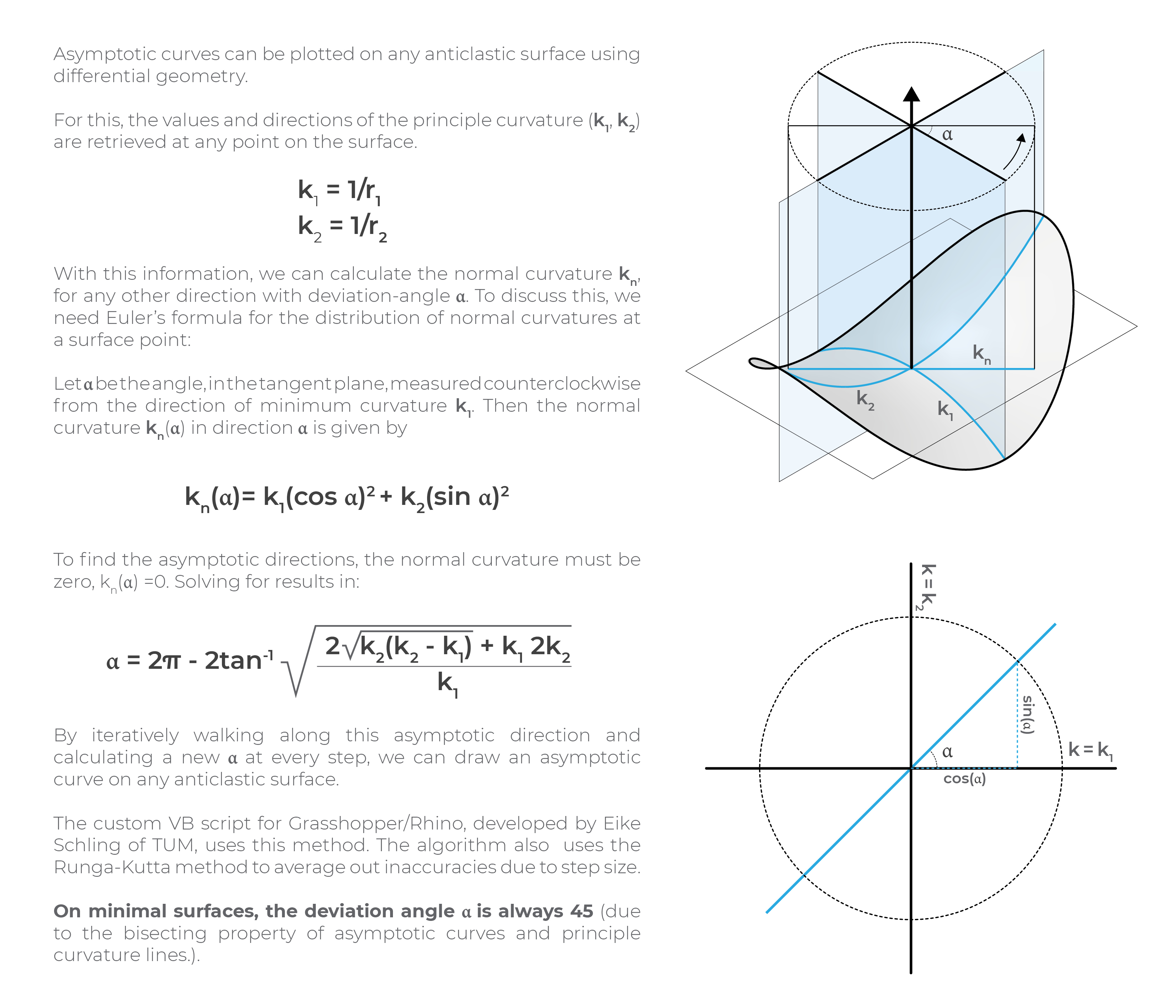
Asymptotic curves can be plotted on any anticlastic surface using differential geometry.
On minimal surfaces, the deviation angle α is always 45 (due to the bisecting property of asymptotic curves and principle curvature lines). Both principle curvature networks and asymptotic curve networks consist of two families of curves that follow a direction field. The designer can only pick a starting point, but cannot alter their path.
(a) Planes of principle curvature are where the curvature takes its maximum and minimum values. They are always perpendicular, and intersect the tangent plane.
(b) Surface geometry at a generic point on a minimal surface. At any point there are two orthogonal principal directions (Blue), along which the curves on the surface are most convex and concave. Their curvature is quantified by the inverse of the radii (R1 and R2) of circles fitted to the sectional curves along these directions. Exactly between these principal directions are the asymptotic directions (orange), along which the surface curves least.
(c) The direction and magnitude for these directions vary between points on a surface.
(d) Starting from point, lines can be drawn to connect points along the paths of principal and asymptotic directions on the respective surface.
Gyroid TPMS
The next step is to create the asymptotic curve network for the Gyroid minimal surface; chosen from my research into Triply Periodic Minimal Surfaces.
As the designer, I can merely pick a starting point on an anticlastic surface from which two asymptotic paths will originate. It is crucial to understand the behaviour of asymptotic curves and its dependency on the Gaussian curvature of the surface.
Through rotational symmetry, it is resolved to only require six unique strips for the complete grid structure (Seven including the repeated perimeter piece).
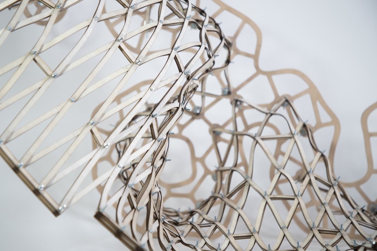
The node to node distance, measured along the asymptotic curves, is the only variable information needed to draw the flat and straight strips. They are then cut flat and bent and twisted into an asymptotic support structure.
Plywood Prototype: 600mm cubed
Eight fundamental units complete the cubit unit cell of a Gyroid surface. Due to the scale of the proposal, I have introduced two layers of lamellas. This is to ensure each layer is sufficiently slender to be easily bent and twisted into its target geometry, whilst providing enough stiffness to resist buckling under compression loads.
‘Minimal Matters’ aims to create an explorative, meditative and interactive experience for visitors. It is a strained grid shell utilising the geometrical benefits of an asymptotic curve network; digitally designed via algorithmic rules to minimise material, cost, and construction time.
Inspired by the highly symmetrical and optimised physical properties of a triply periodic minimal surface, ‘Minimal Matters’ aims to create an explorative, meditative and interactive experience for visitors. It is a strained grid shell utilising the geometrical benefits of an asymptotic curve network; digitally designed via algorithmic rules to minimise material, cost, and construction time.
The proposal takes the form of a crystalline structure found in nature, interpreted through parametric design into a timber grid art piece. In the sense of repeating themselves in three dimensions, a gyroid is an infinitely connected triply periodic minimal surface. A minimal surface is a single surface articulation which minimises that amount of surface needed to occupy space. The proposal represents restoring a balance in energy, taking only that of the earth’s resources required to fulfil the form. Our inability to distinguish our needs from our greeds leads to excessive desires for life’s commodities. The efficiency of the design complements the beauty of rotational symmetry of a single node.
The lattice structure will create foot and hand holds to help climbers onto the series of sloping platforms; allowing users to survey the desert camp from different perspectives.
More than just a climbable structure, Minimal Matters is to be a resting place for festival-goers and a shelter from the strong sun of the site. The layers of grids cast shadows of varied patterns throughout the day. At night, LED lighting along the lamellas will celebrate it’s form and illuminate the playa.
1.5mm Plywood Prototype – 600x600x600mm
Inspired by nature, the proposal brings a parametrically designed structure into the realm of physical interaction. The piece is a culmination of thorough research and physical exploration of timber’s potential. The combination of conceptual bravery matched with architectural reality seeks an architecture of playfulness and beauty which will respond to the inclusive environment of Burning Man. It will celebrate a new design method for timber grid construction, and symbolise the harmony between nature and computational design.
Regarding my previous entries, it can be difficult to see how any of this has to do with architecture. In fact I know a few people who think studying fractals is pointless.
Admittedly I often struggle to explain to people what fractals are, let alone how they can influence the way buildings look. However, I believe that this post really sheds light on how these kinds of studies may directlyinfluence and enhance our understanding (and perhaps even the future) of our built environment.
On a separate note, I heard that a member of the architectural academia said “forget biomimicry, it doesn’t work.”
Firstly, I’m pretty sure Frei Otto would be rolling over in his grave.
Secondly, if someone thinks that biomimicry is useless, it’s because they don’t really understand what biomimicry is. And I think the same can be said regarding the study of fractals. They are closely related fields of study, and I wholeheartedly believe they are fertile grounds for architectural marvels to come.
7.0 Introduction to Shells
As far as classification goes, shells generally fall under the category of two-dimensional shapes. They are defined by a curved surface, where the material is thin in the direction perpendicular to the surface. However, assigning a dimension to certain shells can be tricky, since it kinda depends on how zoomed in you are.
A strainer is a good example of this – a two-dimensional gridshell. But if you zoom in, it is comprised of a series of woven, one-dimensional wires. And if you zoom in even further, you see that each wire is of course comprised of a certain volume of metal.
This is a property shared with many fractals, where their dimension can appear different depending on the level of magnification. And while there’s an infinite variety of possible shells, they are (for the most part) categorizable.
7.1 – Single Curved Surfaces
Analytic geometry is created in relation to Cartesian planes, using mathematical equations and a coordinate systems. Synthetic geometry is essentially free-form geometry (that isn’t defined by coordinates or equations), with the use of a variety of curves called splines. The following shapes were created via Synthetic geometry, where we’re calling our splines ‘u’ and ‘v.’
Uniclastic: Barrel Vault (Cylindrical paraboloid)
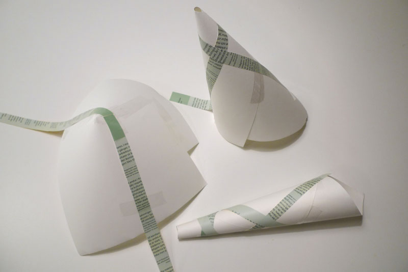
These curves highlight each dimension of the two-dimensional surface. In this case only one of the two ‘curves’ is actually curved, making this shape developable. This means that if, for example, it was made of paper, you could flatten it completely.
Uniclastic: Conoid (Conical paraboloid)
In this case, one of them grows in length, but the other still remains straight. Since one of the dimensions remains straight, it’s still a single curved surface – capable of being flattened without changing the area. Singly curved surfaced may also be referred to as uniclastic or monoclastic.
7.2 – Double Curved Surfaces
These can be classified as synclastic or anticlastic, and are non-developable surfaces. If made of paper, you could not flatten them without tearing, folding or crumpling them.
Synclastic: Dome (Elliptic paraboloid)
In this case, both curves happen to be identical, but what’s important is that both dimensions are curving in the same direction. In this orientation, the dome is also under compression everywhere.
The surface of the earth is double curved, synclastic – non-developable. “The surface of a sphere cannot be represented on a plane without distortion,” a topic explored by Michael Stevens: https://www.youtube.com/watch?v=2lR7s1Y6Zig
Anticlastic: Saddle (Hyperbolic paraboloid)
This one was formed by non-uniformly sweeping a convex parabola along a concave parabola. It’s internal structure will behave differently, depending on the curvature of the shell relative to the shape. Roof shells have compressive stresses along the convex curvature, and tensile stress along the concave curvature.
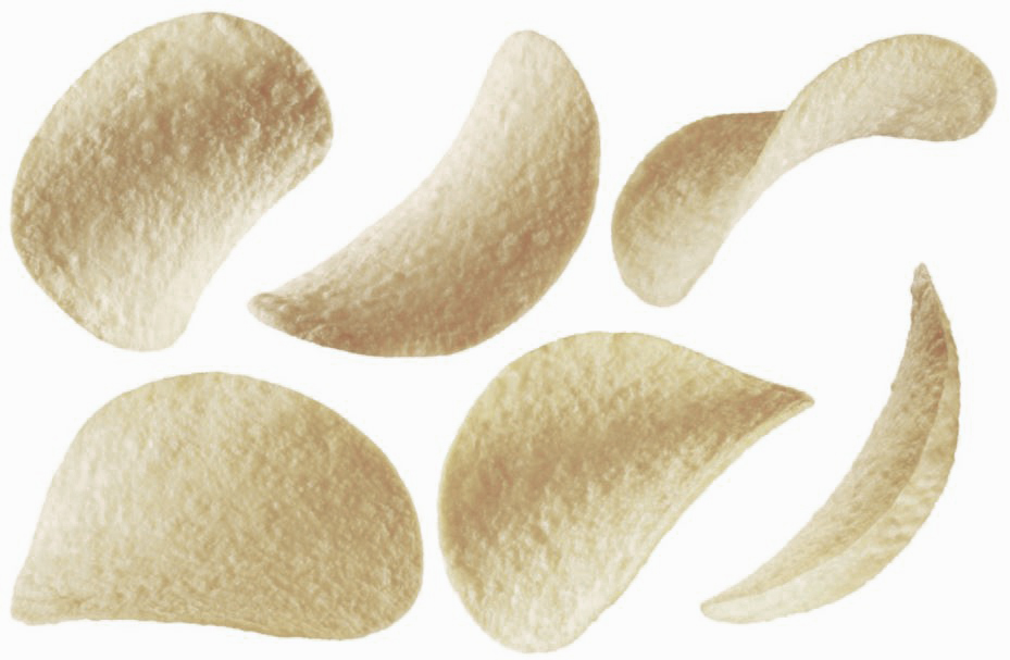
Kellogg’s potato and wheat-based stackable snack
Here is an example of a beautiful marriage of tensile and compressive potato and wheat-based anticlastic forces. Although I hear that Pringle cans are diabolically heinous to recycle, so they are the enemy.
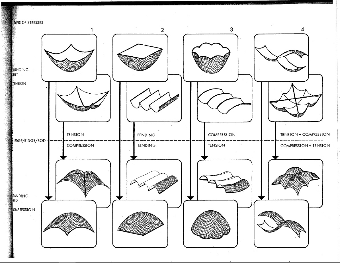
Structural Behaviour of Basic Shells [Source: IL 10 – Institute for Lightweight Structures and Conceptual Design]
7.3 – Translation vs Revolution
In terms of synthetic geometry, there’s more than one approach to generating anticlastic curvature:
Hyperbolic Paraboloid: Straight line sweep variation
This shape was achieved by sweeping a straight line over a straight path at one end, and another straight path at the other. This will work as long as both rails are not parallel. Although I find this shape perplexing; it’s double curvature that you can create with straight lines, yet non-developable, and I can’t explain it..
Ruled Surface & Surface of Revolution (Circular Hyperboloid)
The ruled surface was created by sliding a plane curve (a straight line) along another plane curve (a circle), while keeping the angle between them constant. The surfaces of revolution was simply made by revolving a plane curve around an axis. (Surface of translation also exist, and are similar to ruled surfaces, only the orientation of the curves is kept constant instead of the angle.)
Hyperboloid Generation [Source:Wikipedia]
The hyperboloid has been a popular design choice for (especially nuclear cooling) towers. It has excellent tensile and compressive properties, and can be built with straight members. This makes it relatively cheap and easy to fabricate relative to it’s size and performance.
These are singly curved curves, although that does sound confusing. A simple way to understand what geodesic curves are, is to give them a width. As previously explored, we know that curves can inhabit, and fill, two-dimensional space. However, you can’t really observe the twists and turns of a shape that has no thickness.
Conic Plank Lines (Source: The Geometry of Bending)
A ribbon is essentially a straight line with thickness, and when used to follow the curvature of a surface (as seen above), the result is a plank line. The term ‘plank line’ can be defined as a line with an given width (like a plank of wood) that passes over a surface and does not curve in the tangential plane, and whose width is always tangential to the surface.
Since one-dimensional curves do have an orientation in digital modeling, geodesic curves can be described as the one-dimensional counterpart to plank lines, and can benefit from the same definition.
For simplicity, here’s a basic grid set up on a flat plane:
Basic geodesic curves on a plane
We start by defining two points anywhere along the edge of the surface. Then we find the geodesic curve that joins the pair. Of course it’s trivial in this case, since we’re dealing with a flat surface, but bear with me.
Initial set of curves
We can keep adding pairs of points along the edge. In this case they’re kept evenly spaced and uncrossing for the sake of a cleaner grid.
Addition of secondary set of curves
After that, it’s simply a matter of playing with density, as well as adding an additional set of antagonistic curves. For practicality, each set share the same set of base points.
Grid with independent sets
He’s an example of a grid where each set has their own set of anchors. While this does show the flexibility of a grid, I think it’s far more advantageous for them to share the same base points.
8.2 – Basic Gridshells
The same principle is then applied to a series of surfaces with varied types of curvature.
Uniclastic: Barrel Vault Geodesic Gridshell
First comes the shell (a barrel vault in this case), then comes the grid. The symmetrical nature of this surface translates to a pretty regular (and also symmetrical) gridshell. The use of geodesic curves means that these gridshells can be fabricated using completely straight material, that only necessitate single curvature.
Uniclastic: Conoid Geodesic Gridshell
The same grid used on a conical surface starts to reveal gradual shifts in the geometry’s spacing. The curves always search for the path of least resistance in terms of bending.
Synclastic: Dome Geodesic Gridshell
This case illustrates the nature of geodesic curves quite well. The dome was free-formed with a relatively high degree of curvature. A small change in the location of each anchor point translates to a large change in curvature between them. Each curve looks for the shortest path between each pair (without leaving the surface), but only has access to single curvature.
Anticlastic: Saddle Geodesic Gridshell
Structurally speaking, things get much more interesting with anticlastic curvature. As previously stated, each member will behave differently based on their relative curvature and orientation in relation to the surface. Depending on their location on a gridshell, plank lines can act partly in compression and partly in tension.
On another note:
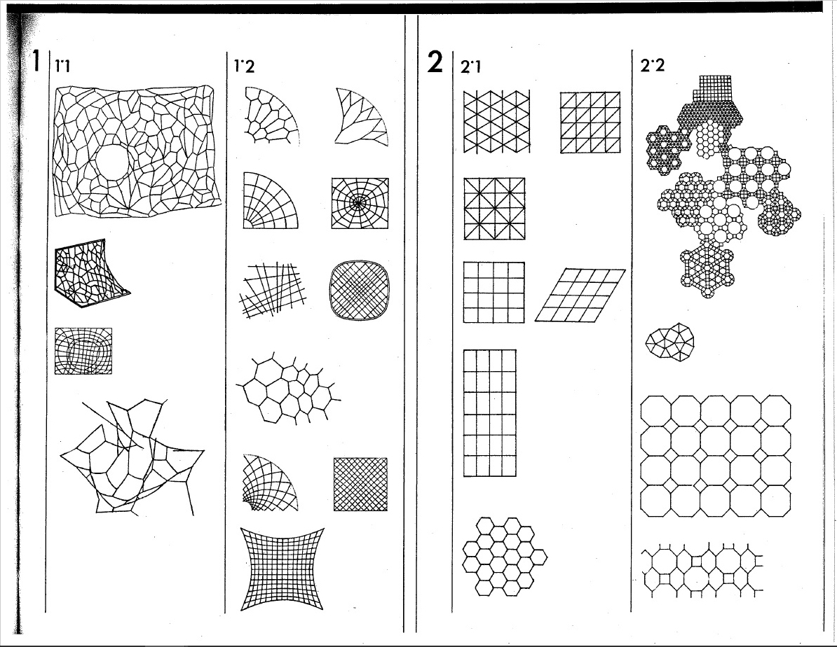
While geodesic curves make it far more practical to fabricate shells, they are not a strict requirement. Using non-geodesic curves just means more time, money, and effort must go into the fabrication of each component. Furthermore, there’s no reason why you can’t use alternate grid patterns. In fact, you could use any pattern under the sun – any motif your heart desires (even tessellated puppies.)
Alternate Gridshell Patterns [Source: IL 10 – Institute for Lightweight Structures and Conceptual Design]
Here are just a few of the endless possible pattern. They all have their advantages and disadvantages in terms of fabrication, as well as structural potential.
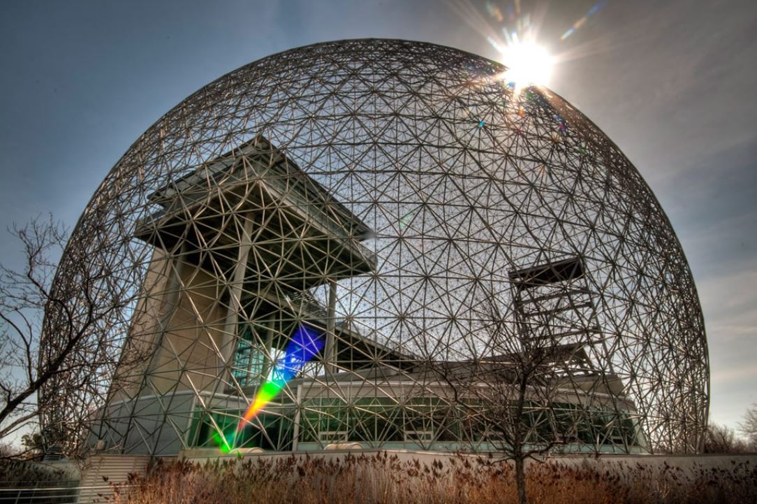
Biosphere Environment Museum – Canada
Gridshells with large amounts of triangulation, such as Buckminster Fuller’s geodesic spheres, typically perform incredibly well structurally. These structure are also highly efficient to manufacture, as their geometry is extremely repetitive.
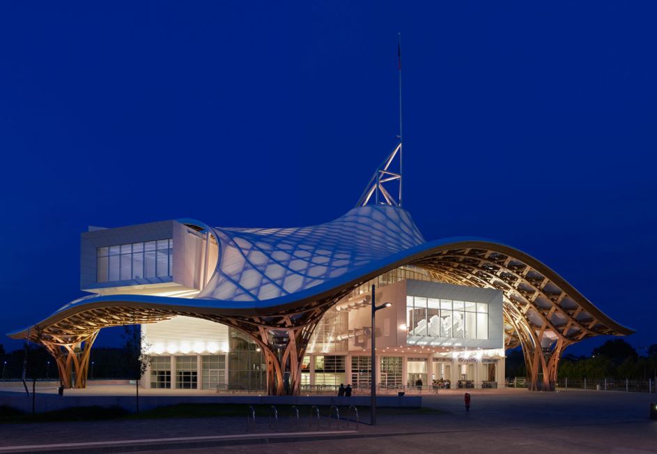
Centre Pompidou-Metz – France
Gridshells with highly irregular geometry are far more challenging to fabricate. In this case, each and every piece had to be custom made to shape; I imagine it must have costed a lot of money, and been a logistical nightmare. Although it is an exceptionally stunning piece of architecture (and a magnificent feat of engineering.)
8.3 – Gridshell Construction
In our case, building these shells is simply a matter of converting the geodesic curves into planks lines.
Hyperbolic Paraboloid: Straight Line Sweep Variation With Rotating Plank Line Grid
The whole point of using them in the first place is so that we can make them out of straight material that don’t necessitate double curvature. This example is rotating so the shape is easier to understand. It’s grid is also rotating to demonstrate the ease at which you can play with the geometry.
Hyperbolic Paraboloid: Flattened Plank Lines With Junctions
This is what you get by taking those plank lines and laying them flat. In this case both sets are the same because the shell happens to the identicall when flipped. Being able to use straight material means far less labour and waste, which translates to faster, and or cheaper, fabrication.
An especially crucial aspect of gridshells is the bracing. Without support in the form of tension ties, cable ties, ring beams, anchors etc., many of these shells can lay flat. This in and of itself is pretty interesting and does lends itself to unique construction challenges and opportunities. This isn’t always the case though, since sometimes it’s the geometry of the joints holding the shape together (like the geodesic spheres.) Sometimes the member are pre-bent (like Pompidou-Metz.) Although pre-bending the timber kinda strikes me as cheating thought.. As if it’s not a genuine, bona fide gridshell.
Toledo Gridshell 2.0. Construction Process [source: Timber gridshells – Numerical simulation, design and construction of a full scale structure]
This is one of the original build method, where the gridshell is assembled flat, lifted into shape, then locked into place.
9.0 Form Finding
Having studied the basics makes exploring increasingly elaborate geometry more intuitive. In principal, most of the shells we’ve looked are known to perform well structurally, but there are strategies we can use to focus specifically on performance optimization.
9.0 – Minimal Surfaces
These are surfaces that are locally area-minimizing – surfaces that have the smallest possible area for a defined boundary. They necessarily have zero mean curvature, i.e. the sum of the principal curvatures at each point is zero. Soap bubbles are a great example of this phenomenon.
Hyperbolic Paraboloid Soap Bubble [Source: Serfio Musmeci’s “Froms With No Name” and “Anti-Polyhedrons”]Soap film inherently forms shapes with the least amount of area needed to occupy space – that minimize the amount of material needed to create an enclosure. Surface tension has physical properties that naturally relax the surface’s curvature.
Kangaroo2 Physics: Surface Tension Simulation
We can simulate surface tension by using a network of curves derived from a given shape. Applying varies material properties to the mesh results in a shape that can behaves like stretchy fabric or soap. Reducing the rest length of each of these curves (while keeping the edges anchored) makes them pull on all of their neighbours, resulting in a locally minimal surface.
Here are a few more examples of minimal surfaces you can generate using different frames (although I’d like stress that the possibilities are extremely infinite.) The first and last iterations may or may not count, depending on which of the many definitions of minimal surfaces you use, since they deal with pressure. You can read about it in much greater detail here: https://tinyurl.com/ya4jfqb2
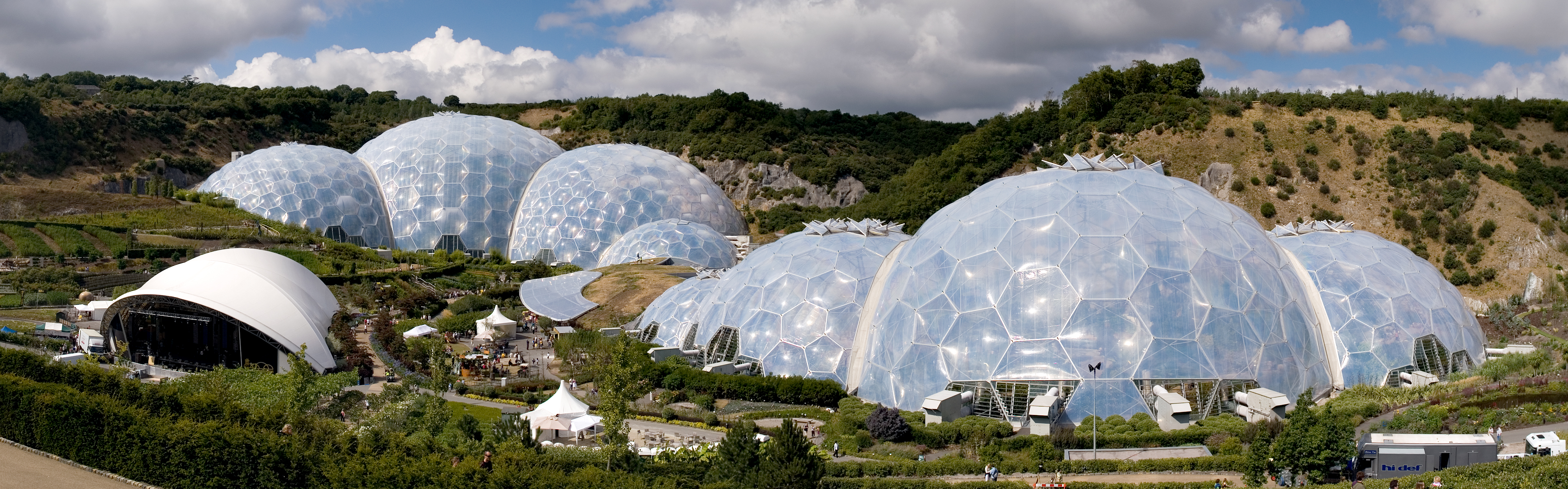
The Eden Project – United Kingdom
Here we have one of the most popular examples of minimal surface geometry in architecture. The shapes of these domes were derived from a series of studies using clustered soap bubbles. The result is a series of enormous shells built with an impressively small amount of material.
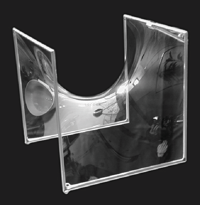
Triply periodic minimal surfaces are also a pretty cool thing (surfaces that have a crystalline structure – that tessellate in three dimensions):
Another powerful method of form finding has been to let gravity dictate the shapes of structures. In physics and geometry, catenary (derived from the Latin word for chain) curves are found by letting a chain, rope or cable, that has been anchored at both end, hang under its own weight. They look similar to parabolic curves, but perform differently.
Kangaroo2 Physics: Catenary Model Simulation
A net shown here in magenta has been anchored by the corners, then draped under simulated gravity. This creates a network of hanging curves that, when converted into a surface, and mirrored, ultimately forms a catenary shell. This geometry can be used to generate a gridshell that performs exceptionally well under compression, as long as the edges are reinforced and the corners are braced.
While I would be remiss to not mention Antoni Gaudí on the subject of catenary structure, his work doesn’t particularly fall under the category of gridshells. Instead I will proceed to gawk over some of the stunning work by Frei Otto.
Of course his work explored a great deal more than just catenary structures, but he is revered for his beautiful work on gridshells. He, along with the Institute for Lightweight Structures, have truly been pioneers on the front of theoretical structural engineering.
9.3 – Biomimicry in Architecture
There are a few different terms that refer to this practice, including biomimetics, bionomics or bionics. In principle they are all more or less the same thing; the practical application of discoveries derived from the study of the natural world (i.e. anything that was not caused or made by humans.) In a way, this is the fundamental essence of the scientific method: to learn by observation.
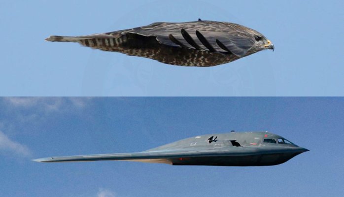
Example of Biomimicry
Frei Otto is a fine example of ecological literacy at its finest. A profound curiosity of the natural world greatly informed his understanding of structural technology. This was all nourished by countless inquisitive and playful investigations into the realm of physics and biology. He even wrote a series of books on the way that the morphology of bird skulls and spiderwebs could be applied to architecture called Biology and Building. His ‘IL‘ series also highlights a deep admiration of the natural world.
Of course he’s the not the only architect renown their fascination of the universe and its secrets; Buckminster Fuller and Antoni Gaudí were also strong proponents of biomimicry, although they probably didn’t use the term (nor is the term important.)
Gaudí’s studies of nature translated into his use of ruled geometrical forms such as hyperbolic paraboloids, hyperboloids, helicoids etc. He suggested that there is no better structure than the trunk of a tree, or a human skeleton. Forms in biology tend to be both exceedingly practical and exceptionally beautiful, and Gaudí spent much of his life discovering how to adapt the language of nature to the structural forms of architecture.
Fractals were also an undisputed recurring theme in his work. This is especially apparent in his most renown piece of work, the Sagrada Familia. The varying complexity of geometry, as well as the particular richness of detail, at different scales is a property uniquely shared with fractal nature.
Antoni Gaudí and his legacy are unquestionably one of a kind, but I don’t think this is a coincidence. I believe the reality is that it is exceptionally difficult to peruse biomimicry, and especially fractal geometry, in a meaningful way in relation to architecture. For this reason there is an abundance of superficial appropriation of organic, and mathematical, structures without a fundamental understanding of their function. At its very worst, an architect’s approach comes down to: ‘I’ll say I got the structure from an animal. Everyone will buy one because of the romance of it.”
That being said, modern day engineers and architects continue to push this envelope, granted with varying levels of success. Although I believe that there is a certain level of inevitability when it comes to how architecture is influenced by natural forms. It has been said that, the more efficient structures and systems become, the more they resemble ones found in nature.
Euclid, the father of geometry, believed that nature itself was the physical manifestation of mathematical law. While this may seems like quite a striking statement, what is significant about it is the relationship between mathematics and the natural world. I like to think that this statement speaks less about the nature of the world and more about the nature of mathematics – that math is our way of expressing how the universe operates, or at least our attempt to do so. After all, Carl Sagan famously suggested that, in the event of extra terrestrial contact, we might use various universal principles and facts of mathematics and science to communicate.
Providing shelter, nutrients, a place to hunt, coral reefs exist in less than 0.1% of our oceans, yet they play host to a quarter of marine species. A wondrous setting for letting the imagination wander, as well as a poignant reminder of the frailty of our beautiful planet, Black Rock Reef invites you to suspend your disbelief, and find your spot in the anemone.
Anemones, more than most components of the reef, share a collaborative relationship with their inhabitants. Their tentacles stun and collect tiny organisms for fish to feed on, and in turn, the fish defend the anemone and waft aerated water past its tentacles with their fins. Once a clown fish has found its anemone, it will never stray farther than four inches from its comforting fingers until it dies.
I hope that the soaring, flexible limbs of Black Rock Reef will prove equally irresistible to the inhabitants of the Playa. The vibrant beacon of color on the horizon serves to draw visitors in from afar, and the intricate arrangement of organic spaces dare further exploration on arrival.
The graceful order of the woven elements provide an incredibly tough surface that is inherently climbable, yet filigree and visually lightweight. Silhouettes of daring explorers who have ascended towards the canopy are visible from afar, inviting others to participate. The curved forms create multiple inhabitable spaces through their relation to one another, the Black Rock Reef has as many inspiring destinations in its topography as your imagination will allow.
Interactivity
Interactivity is integral to the Black Rock Reef. Choosing and then developing a gridshell system has been an exercise in creating a structure that invites and supports climbing and exploring safely.The permeability of the structure makes climbers’ silhouettes clearly visible from afar, a clear visual tutorial for passers by as to the exploratory opportunity offered by the Black Rock Reef.
On closer inspection, the collection of bulging towers lend infinite surfaces to be explored, and each tower’s opening at its base allows the gentle bulges to be experienced from the other side of the skin. A unique interaction of spaces occurs, and people relaxing on a gentle slope may find themselves to be witness to a dramatic ascent of an overhang, through the apertures in their seat!
The interior of the cores also serve as ladders to the canopy of the reef, which is an enclosed bowl with spectacular views across the playa, with space for several simultaneous inhabitants. The gently sloping of the canopy perimeter serves to gently enclose even the wobbliest burner, without intrusively caging, or breaking the connection with the external environment.
An optional in-situ burn of the Black Rock reef would prove spectacular, with the woven structure allowing for an air fuelled ferocious burn. Burn safe methods of colouring the laths would be sought, if a burn was planned.
1:5 Scale model of structural system
Lath fabrication and pre-fab element assembly and transportation
On-site pre-fab element assembly procedure
Evening at the reef
At night the towers are lit from beneath, creating a colourful beacon visible from afar. The intricate gridshell surfaces cast spectacularly kaleidoscopic geometric shadows.
As anyone who has been lucky enough to scuba dive at night with a torch will understand, the colour and form of the Black Rock Reef will really come to life at night, with dizzyingly complex shadow patterns cast against an uplifting splash of colour.
We just finished our last tutorials of the first term! Congratulations to all the students for the great three months and looking forward to the remaining two terms.
Students completed both briefs (brief01:systems and brief2A:festival) and are starting the case studies of events as part of our last brief (brief2B:realise).
Here are couple pictures of the projects we have seen during the last tutorials. Where do you suggest building the structures over the summer?
Merry Christmas & best wishes for the New Year!!
John Konings’s towering gridshell.
John Konings’s towering gridshell.
John Konings’s towering gridshell.
Andres Jippa’s 3D prints, driven by Chaos theory’s strange attractors.
Andres Jippa’s 3D prints, driven by Chaos theory’s strange attractors.
Andres Jippa’s 3D prints, driven by Chaos theory’s strange attractors.
Andres Jippa’s 3D prints, driven by Chaos theory’s strange attractors.
Andres Jippa’s 3D prints, driven by Chaos theory’s strange attractors.
Andres Jippa’s 3D prints, driven by Chaos theory’s strange attractors. Construction Component.
Henry Turner’s Curved Intersecting Plywood Wave Structure
Ieva Ciocyte’s Flame Tower made of Intersecting plywood components
Sarah Shuttleworth’s Moebius Strips made of Steel Stars.
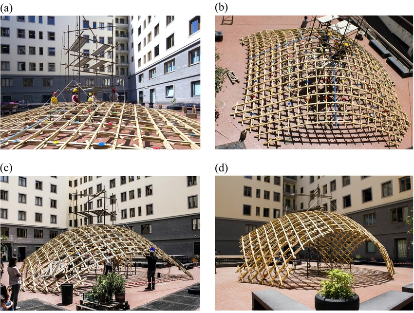
William Garforth-Bless’ Bamboo Hammock Amphitheatre
William Garforth-Bless’ Bamboo Hammock Amphitheatre
As part of an investigation into gridshells I posted in the Grasshopper forum to try and find a solution to a definition using the bend force component through the Kangaroo plug-in for Grasshopper.
My intention was to deform a grid into lathes using a bend force whilst maintaining the overall length of each lathe (or curve) as a representation of how gridshell are constructed on site, where they are raised or lowered into position from an originally flat grid, and deform or bend due to their own self weight.
Daniel Piker the creator of Kangaroo replied with a very useful script component that allows the user to easily find the correct inputs for a divided curve that is plugged into the bend component.
He also very kindly finished the definition for me.
The files including the C# script component can be found in the forum post here if you would also like to investigate the bend force.
The videos are from the workshop I attended in April. This particular video shows Michael Grau’s robot, which basically draws the intersection points along a wooden member as slashes in the right or left direction and writes a code consisting of a number and a letter, so later on when it came down to putting the structure together we knew exactly where and what direction to put the wooden members in. Time was running out so we used cable ties for both constructions. The final structure is a very organic form.
The second construction was created by studying people and their movements on the site at Hooke park, the movements were 3d scanned using a hacked Kinect Xbox (acted as a motion sensor), then points were generated in Rhino to form a point cloud model. The points were joined together with lines forming a voronoi (a volume,form). We then used a robot which took the coordinates of each member from the computer and translated these to the space in the forest, it moved within the perimeter of the site and told us where to position each wooden member, so we cut the wood as we went along and connected each member with an eyehook and a cable tie. Sometimes additional support was required that the computer did not account for, so we just added these. Also in the organic form the material used was not flexible enough to create the rounded shapes, as a result the structure kept breaking in sections and we had to add additional supports.
If we had more time it would have been ideal to test different types of material.