The Palm Arms


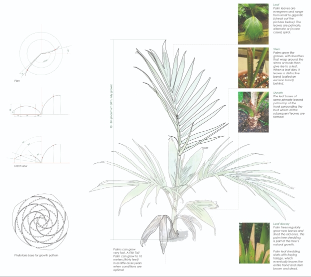
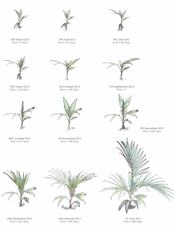
Palm trees are angiosperms, which means flowering plants. They are monocots which means their seeds produce a single, leaf-like cotyledon when they sprout. This makes palms closely related to grasses and bamboo.

Palm Tree
Components of Palm Trees
Growth and Decay
Palm Growth and Decay Process
Palm Tree Information

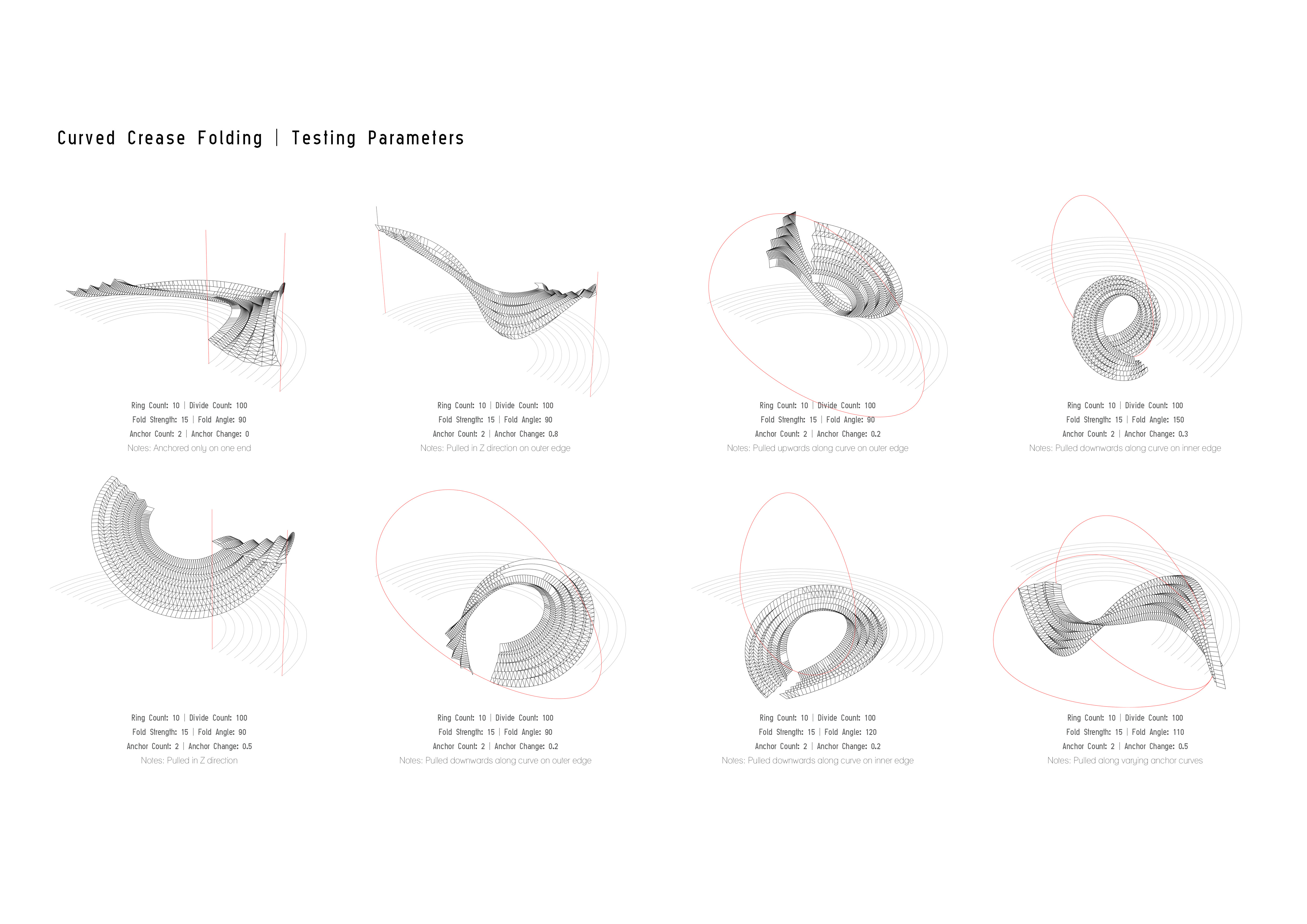
Mimicking the Geometry

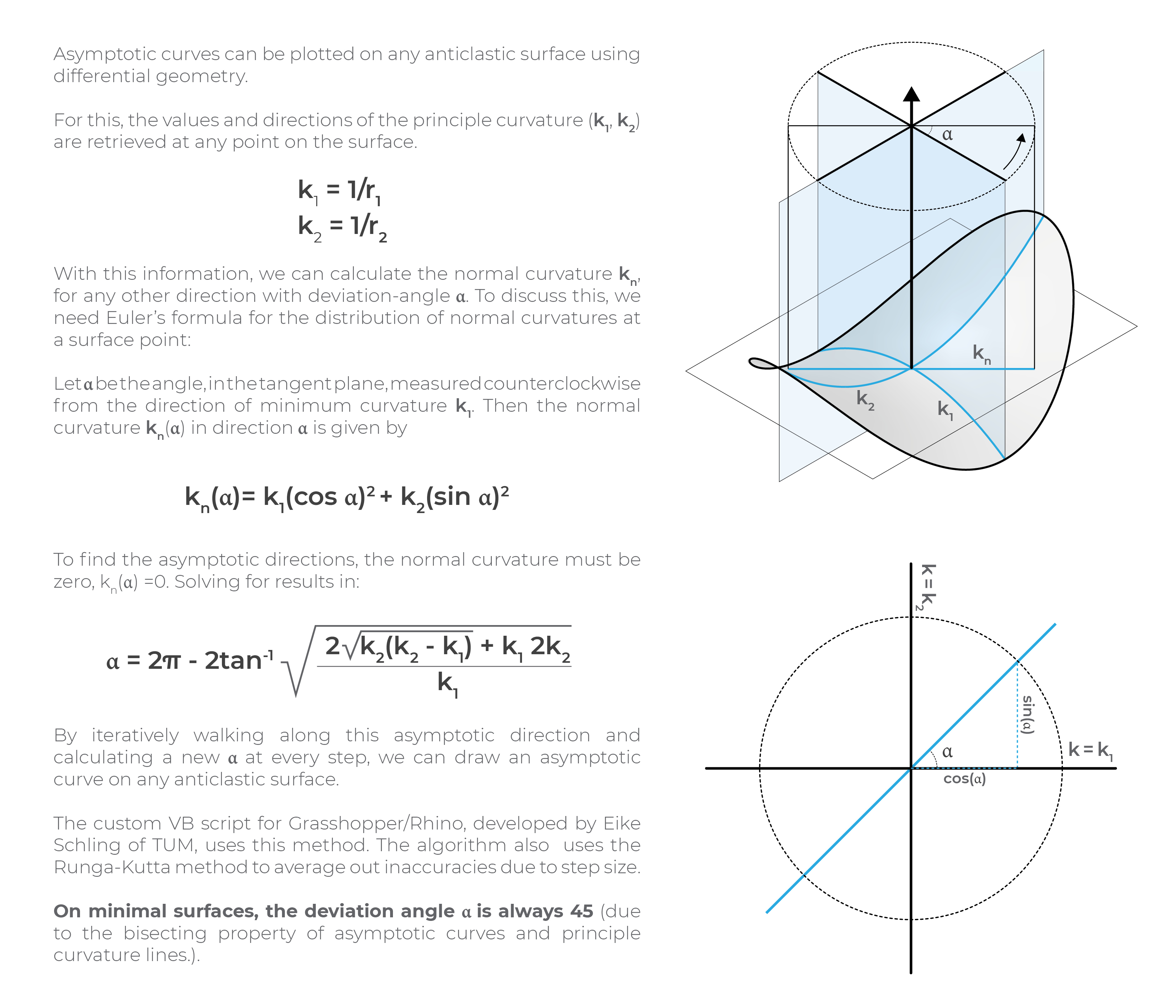
This mature palm shows how the pattern originally seen in the young plant, forms a distinct mathematic pattern known as ‘Phyllotaxis’. This is a pattern with reoccurs throughout nature and is based on the Fibonacci sequence. In order to try to understand the use and formation of the palm fibre, the overall formation of the palm stem needed to be mathematically explored.

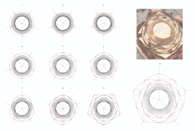
However, redrawing the cross-section of the base of the palm plants allows a better understanding of the arrangement of the palm plant.

Frond Arrangement
Palm Frond Arrangement

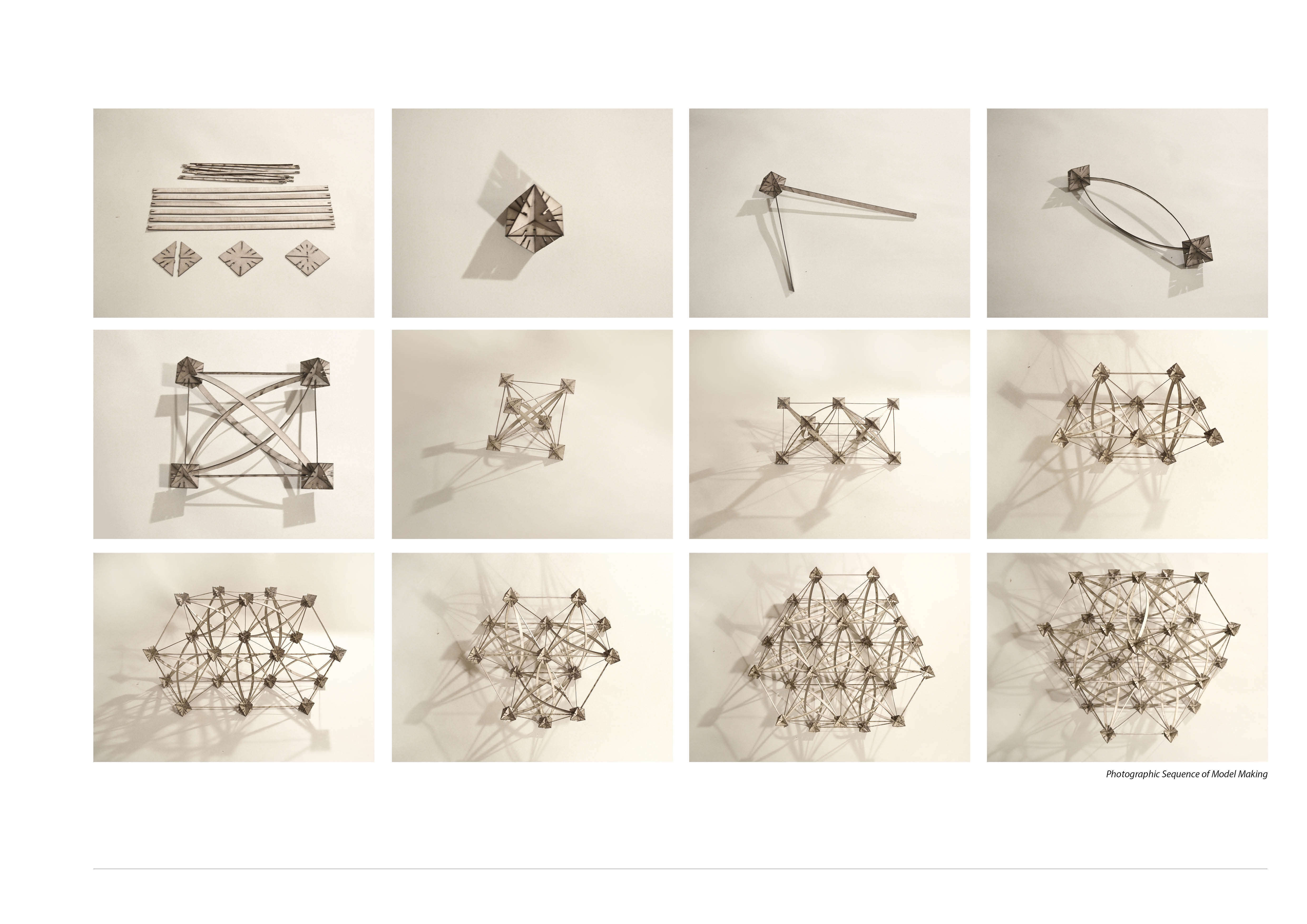
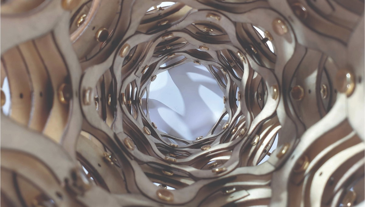
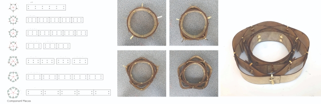
This exercise allows models to be made to recreate the patterns found in palm plants. By engineering plywood components, the basic shape of the palm geometry can be made into a physical model.

Palm Base Model
Re-creating Palm Base

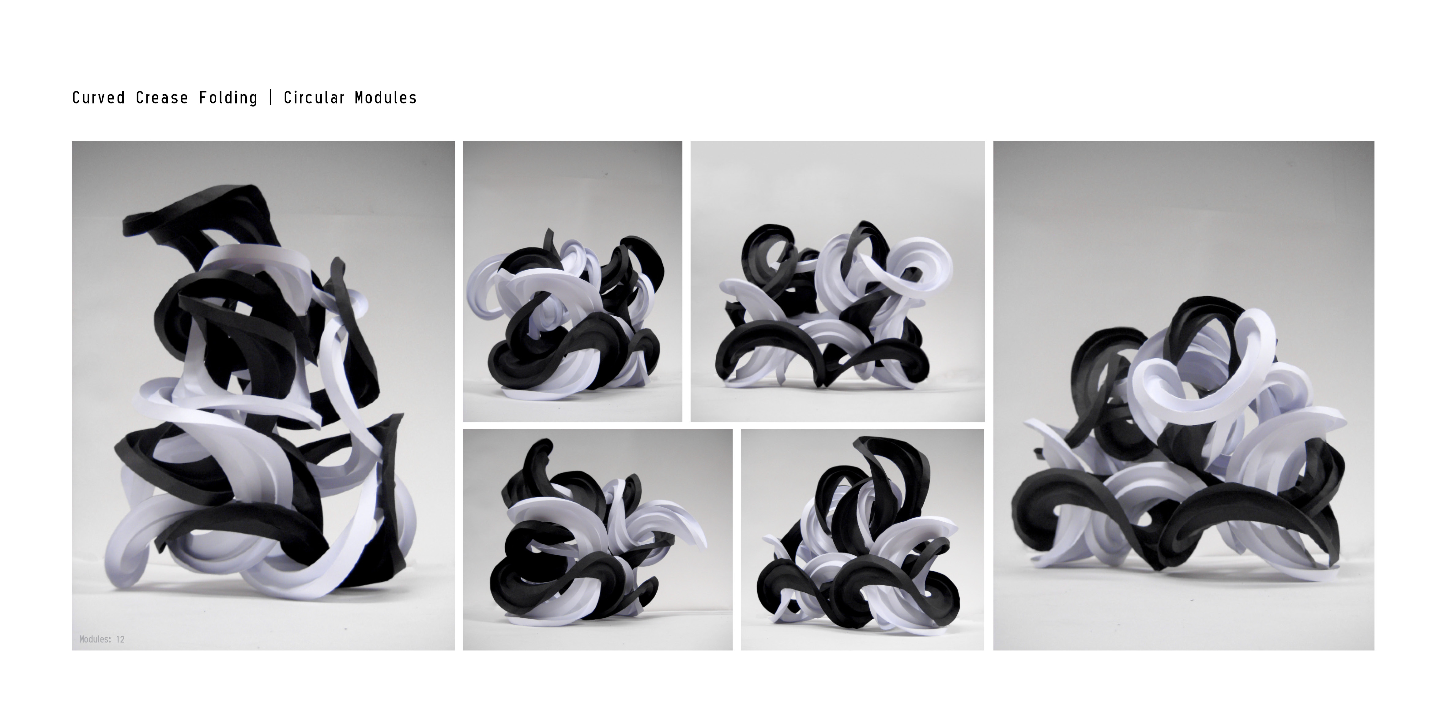
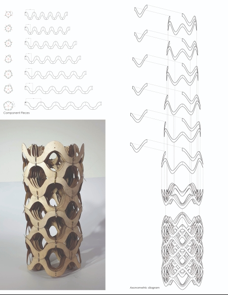
This was pushed further by curving the plywood components to make extruded palm structure models

Palm Structure Model
Extended Palm Structure Model
Palm Structure Model
Three-Dimensional Palm Model

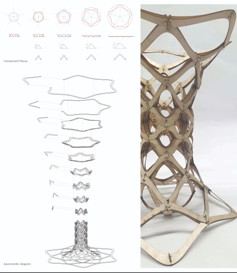
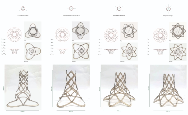
The arrayed components can then be altered so that the base of the models form regular polygon shapes. Doing this allows the potential for the structures to be tesselated. Using different numbers of components mean the structure can then be tested for strength.
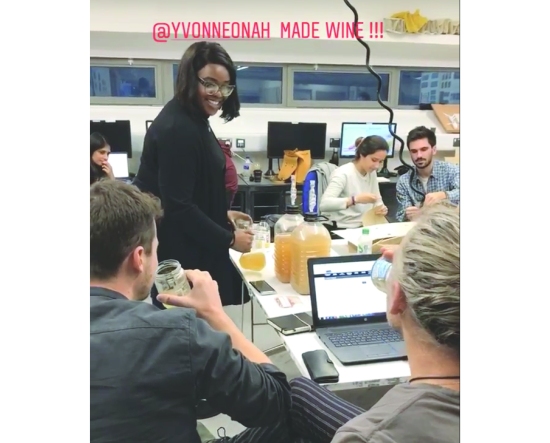
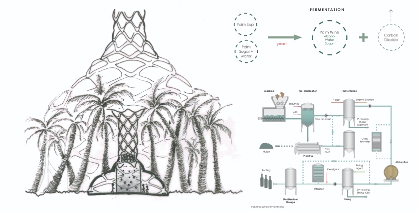
Tessellation Models
Tessellation Models

Palm Wine

There are hundreds of used for palm fruits, this the plant producing materials which range from durable, to flexible to edible. One of the more interesting ones if the production of palm wine using the sap from the tree. Within 2 hours of the wine tapping process, the wine may reach up to 4%, by the following day the palm wine will become over fermented. Some prefer to drink the beverage at this point due to the higher alcohol content. The wine immediately begins fermenting, both from natural yeast in the air and from the remnants of wine left in the containers to add flavour. Ogogoro described a ‘local gin’, is a much stronger spirit made from Raffia palm tree sap. After extraction, the sap is boiled to form steam, which is then condensed and collected for consumption. Ogogoro is not synthetic ethanol but it is tapped from a natural source and then distilled.

To understand the fermentation process more clear, the process of fermenting sugar to make wine has been undertaken.
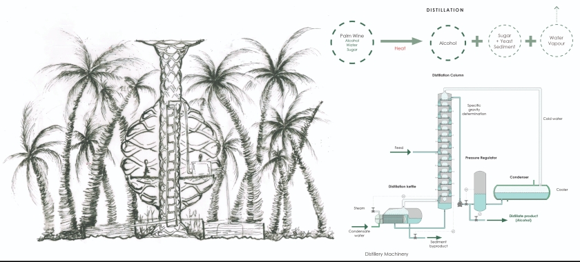
Palm wine tasting
Testing Palm Wine

Alternative Fuel

The distillation of the wine can be used to make bio-ethanol. This production of this fuel can act as a sustainable alternative to fossil fuel energy, which is overused and damaging to our environment.
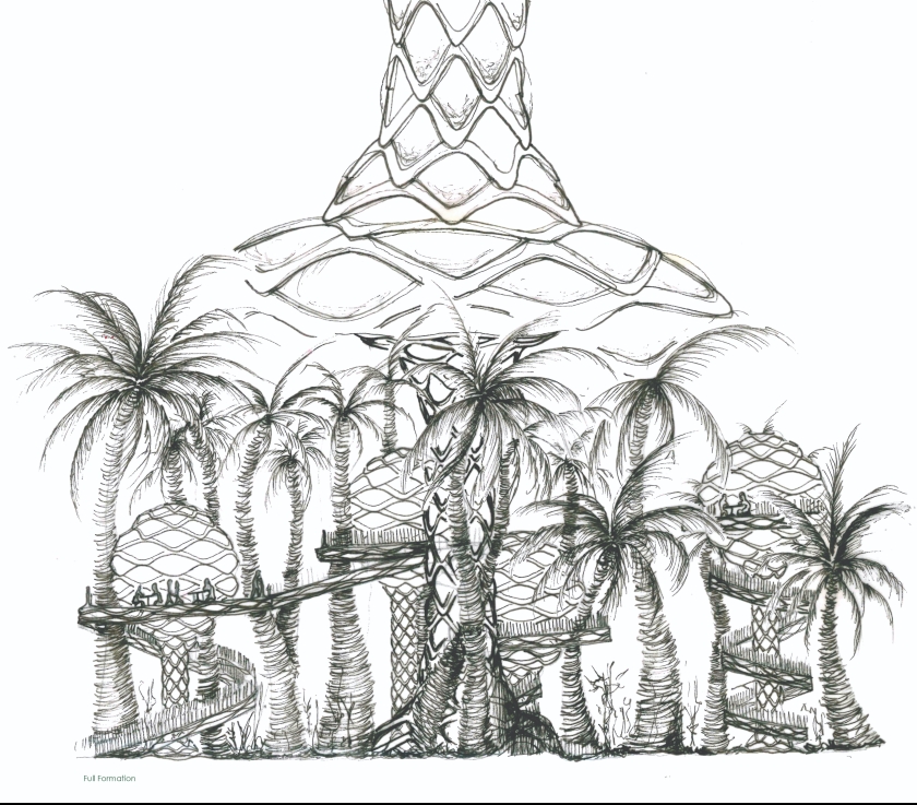
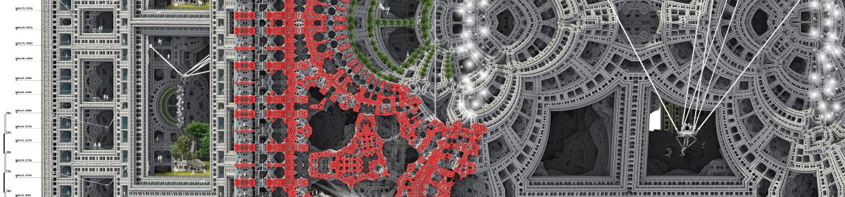
Energy
How Much Energy?

Future Proposal

The developed structure, as well as the production of palm wine and bio-ethanol, can be collaborated to develop a programme, which provides sustainable energy, within a space that is inviting and exciting.

The production of bio-fuel releases a lot of carbon dioxide. In order to ensure the process does not impact the environment, this needs to occur inside a closed system, so the CO2 does not enter the atmosphere. This can be done by using the properties of a Solar Updraft Tower. Carbon dioxide released from the fermentation and distillation processes can be received by palm trees for increased photosynthesis, while the excess oxygen from the trees provides fresh air for visitors.


Solar Updraft Tower Implementation
Form 01 – Solar Updraft Tower Implementation


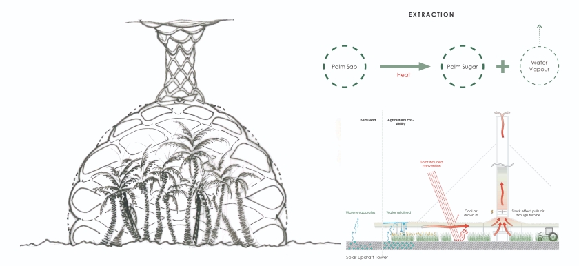
The fermentation process can be controlled within an isolated area of the model.

Fermentation Implementation
Form 02 – Fermentation Implementation


The Distillation process, which requires a store of water for cooling, can also be conducted in an isolated area of the model, with apparatus incorporated into the structure.

Distillation Implementation
Form 03 – Distillation Implementation


The final proposal will be a combination of all three forms


Proposal
Proposal

Asymptotic Grid Structure of a Triply Periodic Minimal Surface

Through extensive research into the construction of grid shells, as well as differential geometry, I present a design solution for a complex grid structure inspired by the highly symmetrical and optimised physical properties of a triply periodic minimal surface. The proposal implements the asymptotic design method of Eike Schling and his team at Technical University of Munich.

‘Minimal Matters’ utilises the several geometric benefits of an asymptotic curve network to optimise cost and fabrication. From differential geometry, it is determined asymptotic curves are not curved in the surface normal direction. As opposed to traditional gridshells, this means they can be formed from straight, planar strips perpendicular to the surface. In combination with 90° intersections that appear on all minimal surfaces (soap films) this method offers a simple and affordable construction method. Asymptotic curves have a vanishing normal curvature, and thus only exist on anticlastic surface-regions. 

Asymptotic curves can be plotted on any anticlastic surface using differential geometry.

On minimal surfaces, the deviation angle α is always 45 (due to the bisecting property of asymptotic curves and principle curvature lines). Both principle curvature networks and asymptotic curve networks consist of two families of curves that follow a direction field. The designer can only pick a starting point, but cannot alter their path.

(a) Planes of principle curvature are where the curvature takes its maximum and minimum values. They are always perpendicular, and intersect the tangent plane.

(b) Surface geometry at a generic point on a minimal surface. At any point there are two orthogonal principal directions (Blue), along which the curves on the surface are most convex and concave.
Their curvature is quantified by the inverse of the radii (R1 and R2) of circles fitted to the sectional curves along these directions. Exactly between these principal directions are the asymptotic directions (orange), along which the surface curves least.

(c) The direction and magnitude for these directions vary between points on a surface.

(d) Starting from point, lines can be drawn to connect points along the paths of principal and asymptotic directions on the respective surface.

Gyroid TPMS

The next step is to create the asymptotic curve network for the Gyroid minimal surface; chosen from my research into Triply Periodic Minimal Surfaces.

As the designer, I can merely pick a starting point on an anticlastic surface from which two asymptotic paths will originate. It is crucial to understand the behaviour of asymptotic curves and its dependency on the Gaussian curvature of the surface.

Through rotational symmetry, it is resolved to only require six unique strips for the complete grid structure (Seven including the repeated perimeter piece).

The node to node distance, measured along the asymptotic curves, is the only variable information needed to draw the flat and straight strips. They are then cut flat and bent and twisted into an asymptotic support structure.

Plywood Prototype: 600mm cubed

Eight fundamental units complete the cubit unit cell of a Gyroid surface. Due to the scale of the proposal, I have introduced two layers of lamellas. This is to ensure each layer is sufficiently slender to be easily bent and twisted into its target geometry, whilst providing enough stiffness to resist buckling under compression loads.

‘Minimal Matters’ aims to create an explorative, meditative and interactive experience for visitors. It is a strained grid shell utilising the geometrical benefits of an asymptotic curve network; digitally designed via algorithmic rules to minimise material, cost, and construction time.

Minimal Matters: Burning Man Proposal

Inspired by the highly symmetrical and optimised physical properties of a triply periodic minimal surface, ‘Minimal Matters’ aims to create an explorative, meditative and interactive experience for visitors. It is a strained grid shell utilising the geometrical benefits of an asymptotic curve network; digitally designed via algorithmic rules to minimise material, cost, and construction time.

The proposal takes the form of a crystalline structure found in nature, interpreted through parametric design into a timber grid art piece. In the sense of repeating themselves in three dimensions, a gyroid is an infinitely connected triply periodic minimal surface. A minimal surface is a single surface articulation which minimises that amount of surface needed to occupy space. The proposal represents restoring a balance in energy, taking only that of the earth’s resources required to fulfil the form. Our inability to distinguish our needs from our greeds leads to excessive desires for life’s commodities. The efficiency of the design complements the beauty of rotational symmetry of a single node.

The lattice structure will create foot and hand holds to help climbers onto the series of sloping platforms; allowing users to survey the desert camp from different perspectives.

More than just a climbable structure, Minimal Matters is to be a resting place for festival-goers and a shelter from the strong sun of the site. The layers of grids cast shadows of varied patterns throughout the day. At night, LED lighting along the lamellas will celebrate it’s form and illuminate the playa.

1.5mm Plywood Prototype – 600x600x600mm


Inspired by nature, the proposal brings a parametrically designed structure into the realm of physical interaction. The piece is a culmination of thorough research and physical exploration of timber’s potential. The combination of conceptual bravery matched with architectural reality seeks an architecture of playfulness and beauty which will respond to the inclusive environment of Burning Man. It will celebrate a new design method for timber grid construction, and symbolise the harmony between nature and computational design.

Bending Lattice System

My initial studies stemmed from researching into Stellation. This, in simple terms, is the process of extending  polygon in two dimensions, polyhedron in three dimensions, or, in general, a polytope in n dimensions, to form a new figure. Through researching the application of this process, I came across the sculptures created by George Hart, as he has experimented with stellated geometries to which are subdivided to create mathematical interweaving structures.Stellation 1

My Research into the method and calculations of George Hart’s Mathematical Sculpture’s focused on the sculpture ‘Frabjous’. Through rigorous testing and model making I have understood the rules behind the complex form. This is based on the form of a stellated icosahedron, whose shape is contained within a dodecahedron.grey card model

Lines are drawn from one point, to a point mirrored at one edge of the face of the dodecahedron form – as shown in the diagram. This creates intersecting lines at each face as you can see from the diagrams below. Each dividing line has two intersection points, with symmetry at the center of the line. The sculpture aims to avoid the intersections of these lines by introducing a sine curve with the domain 0 to 2*pi. As you can see, each component is exactly the same – for this model, 30 components are used.

george hart diagram 1george hart diagram 2george hart diagram 3

`To simplify the construction of the sculpture, I extracted a build-able section which uses ten components in total. Two of these sections are then weaved together and joined up by a further ten single components to form the entire sculpture.Diagram Sequence of Researched SculptureOne Component ImageryGeometry 2

Following this research, I extracted the concept of avoiding the intersection and subdivided a cube with lines from each corner of the cube. These lines were then weaved around eachother using a sine curve with a domain of 0 to pi. I then mirrored the curves and rotated them to create an intertwining form.Avoiding Self Intersection 2

Another test was created with the same process, however subdividing a cube using the midpoint of each face. – This creates an octahedral geometry.Avoiding Self Intersection octahedron

Using this interweaving geometry, I have created different three dimensional arrays to create a spatial form. The concept of avoiding intersections naturally cause a structure to fail. To form a structurally efficient version of this geometry, I introduced the idea of a reciprocal structure, and allowed the beams to self support by resting on eachother. This did not create a structure strong enough to stand on, however through adding a cube whose dimensions are equal to the width of the beams, the structure became very strong.

Avoiding Self Intersection octahedron 3

Testing the component at a small scale required the design of a joint which allowed me to assemble these components together through interlocking elements. Each beam element slots into the joint; When two joints and two beams are connected together the curves naturally stay in place due to the angle cut into the joint. Three of these connected elements together form the component.

Diagraming the Joint

As mentioned previously, avoiding intersections create inefficient structures – For this small scale experimentation, the concept of Tensegrity was implemented. Tensegrity is a structural principle based on using isolated compression components within a net of continuous tension, allowing the compression members to not need to touch each other. This model was constructed using 1.5mm plywood which has been laser cut; the modularity of the system ensures minimal material wastage.

Construction Sequence of ModelModel Photographs

The three dimensional array of this geometry creates many interesting shapes and patterns when viewed from different angles – this is visible in the following video:


Curved Crease Folding

The history of curved crease folding goes back to as early as the Bauhaus, where a student had scored circular creases onto a paper in order to study its materiality. When a circular surface is folded along concentric rings, the resultant form bends on itself and forms a paraboloid in order to make up for the loss in circumference. Initial investigation involved the replication of such system and multiplying the modules which are then interlocked into each other to create various origami sculptures.

Circular Modules

Circular Modules

The system is then digitally simulated in order to extract the parameters which may affect the resultant geometry of the surface. With a combination of Kangaroo Physics, Hinge Forces and Springs, the digital simulation is created which allows anchor points to be placed, thus dragging for surface into various forms. Tests are carried out on different surfaces, including a closed circle of equal concentric rings, a closed circle of increasing concentric rings as well as an open circular strip with concentric rings. With an increasing fold angle, the bend angle increases.

System Exploration

System Exploration2

System Exploration

System Exploration

Upon cutting the closed circle, the surface becomes an open ended circular strip. The constraints that follow a closed surface no longer presents itself, thus allowing the strip to bend freely – although the principles of the system still applies. With increasing fold angles, the strip bends at greater angle. Having this revelation, different open ended strips are then tested against different parameters to extract the system further.

Parameters

Parameters

Parameters

Parameters

Parameters

In parallel to the research of curved crease folding is the investigation into the probability of transferring the system onto a more rigid, larger material, such as plywood. Here lattice hinge / kerf folds are employed, allowing the plywood to bend in a similar manner to card and paper. The final patterns for the hinges are a result of rigorous testing through trial and error. By repeating the modules we begin to see that, due to the folds, plywood can be as flexible as card.

Lattice

Lattice

System Development: Spidron

First developed in 1979 by Dániel Erdély the Spidron is created by recursively dividing a 2-dimensional hexagon into triangles, forming a pattern that consists of one equilateral followed by one isosceles triangle. The resulting form is of six Spidron legs that, when folded along their edges, deform to create a 3-dimensional Spidron.

Spidron Nest

Spidron System_Parametrics_Lorna Jackson

Initial investigations into the Spidron system using paper resulted in irregular shapes that could not be predicted, and therefore replicated precisely. Progressing onto using rigid materials allowed the system to be broken down into six components, removing unnecessary triangulated fold lines, and developing latch folded Spidron that is precisely the same as that formed parametrically.

Spidron System_Three SPidrons_Lorna Jackson

This relationship between parametric and physical tests of component based Spidrons in both regular and irregular hexagons, as well as various other equal-sided shapes, has enabled the development of large scale models concluding thus far in a 1:2 scale version being built which will continue to be developed as a pavilion for submission to the Burning Man festival.

In parallel there has been an investigation into the system at a smaller scale allowing for the Spidron nest to be made as one component. In order to achieve the 3-dimensional Spidron form lattice hinges, also known as kerf folds, have been employed. Rigorous testing into the best cutting pattern have resulted in a straight line cutting pattern that allows for bending on multiple axis at once.

Developing this smaller scale system for submission to Buro Happold the intention is to create an arrayed system that is a conglomeration of both regular and irregular spidrons with varying depths and apertures that are able to integrate various display models etc. within.

WeWantToLearn.net wins Burning Man Art Grant for the second year

Toby Burgess and I are very happy to announce that HAYAM – Temple to Sunlight, designed by Josh Haywood of Diploma Studio 10, University of Westminster, has won the Burning Man Art Grant. Similarly to last year’s amazing experience building Shipwreck and Fractal Cult, we will develop the project with the help of engineers at Ramboll Computational Design and will travel to Burning Man in August to realize the project. Josh Haywood has just sent the great pictures below of the latest prototypes in which we are lashing the plywood pieces together.


Josh Haywood - WeWantToLearn.net - Hayam, Temple to Sunshine for Burning Man 2014
Josh Haywood – WeWantToLearn.net – Hayam, Temple to Sunlight for Burning Man 2014

Josh Haywood - WeWantToLearn.net - Hayam, Temple to Sunshine for Burning Man 2014
Josh Haywood – WeWantToLearn.net – Hayam, Temple to Sunlight for Burning Man 2014

Josh Haywood - WeWantToLearn.net - Hayam, Temple to Sunshine for Burning Man 2014
Josh Haywood – WeWantToLearn.net – Hayam, Temple to Sunlight for Burning Man 2014

Josh Haywood - WeWantToLearn.net - Hayam, Temple to Sunshine for Burning Man 2014
Josh Haywood – WeWantToLearn.net – Hayam, Temple to Sunlight for Burning Man 2014

Toby and I explain the reason behind these projects in the TedX video below, The Architecture of Joy:


As the grant is limited, we need your help to pay for transportation and the additional costs related to construction, you can donate on the PayPal button below:

16th January 2014 Tutorial

Happy new year! We are back and had our first tutorials session today. Students are submitting their portfolio on Tuesday and have started the last brief (see all our briefs for the year here). Here are two projects which are worth sharing for the following reasons:

  • Ieva Ciocyte’s elevation and plan drawings are very clear, with attention to details: traced Burning Man people, perfect shadows and lineweights, labels and dimensions. It just looks good.
  • Andrei Jipa manipulated the G-Code of his 3D Prints to create a continuous extrusion. Instead of slicing the prints horizontally, he generated a print path that follows the geometry and goes up in a spiral.

More beautiful projects on Tuesday evening!

Elevation 1 - Ieva Ciocyte Interlocking Plywood Tower
Elevation  1  – Ieva Ciocyte Interlocking Plywood Components Tower

Elevation 1 - Ieva Ciocyte Interlocking Plywood Tower
Elevation 2 – Ieva Ciocyte Interlocking Plywood Components Tower

Plan - Ieva Ciocyte Interlocking Plywood Tower
Plan – Ieva Ciocyte Interlocking Plywood Components Tower

Andrei Jippa's 3D printed intersecting component - Strange Attractors
Andrei Jipa’s 3D printed intersecting components made from a custom G-Code and used for his Strange Attractors pavilion

Andrei Jippa's 3D printed intersecting component - Strange Attractors
Andrei Jipa’s 3D printed intersecting components made from a custom G-Code and used for his Strange Attractors pavilion

Andrei Jippa's 3D printed intersecting component - Strange Attractors
Andrei Jipa’s 3D printed intersecting components made from a custom G-Code and used for his Strange Attractors pavilion

Thursday 12th December 2013

We just finished our last tutorials of the first term! Congratulations to all the students for the great three months and looking forward to the remaining two terms.

Students completed both briefs (brief01:systems and brief2A:festival) and are starting the case studies of events as part of our last brief (brief2B:realise).

Here are couple pictures of the projects we have seen during the last tutorials. Where do you suggest building the structures over the summer?

Merry Christmas & best wishes for the New Year!!

John Konings's towering gridshell.
John Konings’s towering gridshell.

John Konings's towering gridshell.
John Konings’s towering gridshell.

John Konings's towering gridshell.
John Konings’s towering gridshell.

Andres Jippa's 3D prints, driven by Chaos theory's strange attractors.
Andres Jippa’s 3D prints, driven by Chaos theory’s strange attractors.

Andres Jippa's 3D prints, driven by Chaos theory's strange attractors.
Andres Jippa’s 3D prints, driven by Chaos theory’s strange attractors.

Andres Jippa's 3D prints, driven by Chaos theory's strange attractors.
Andres Jippa’s 3D prints, driven by Chaos theory’s strange attractors.

Andres Jippa's 3D prints, driven by Chaos theory's strange attractors.
Andres Jippa’s 3D prints, driven by Chaos theory’s strange attractors.

Andres Jippa's 3D prints, driven by Chaos theory's strange attractors.
Andres Jippa’s 3D prints, driven by Chaos theory’s strange attractors.

Andres Jippa's 3D prints, driven by Chaos theory's strange attractors. Construction Component.
Andres Jippa’s 3D prints, driven by Chaos theory’s strange attractors. Construction Component.

Henry Turner's Curved Intersecting Plywood Wave Structure
Henry Turner’s Curved Intersecting Plywood Wave Structure

Ieva Ciocyte's Flame Tower made of Intersecting plywood components
Ieva Ciocyte’s Flame Tower made of Intersecting plywood components

Sarah Shuttleworth's Moebius Strips made of Steel Stars.
Sarah Shuttleworth’s Moebius Strips made of Steel Stars.

William Garforth-Bless' Bamboo Hammock Amphitheatre
William Garforth-Bless’ Bamboo Hammock Amphitheatre

William Garforth-Bless' Bamboo Hammock Amphitheatre
William Garforth-Bless’ Bamboo Hammock Amphitheatre

28th November 2013 Cross-Crit 2

Very enjoyable crit day for DS10 at Westminster University. It was our second cross-crit of the year and students showed their proposal for Brief2A, building an interactive structure for Burning Man or the festival of their choice.

Thank you very much to our helpful crits Harri Lewis (Ramboll RCD our engineers for last year’s Shipwreck and Fractal Cult), Marie-Isabel de Monseignat (Tutor at DRS1 Chelsea College of Art), Dusan Decermic, Anthony Boulanger and Katherine Herron. Here are couple pictures:

Marie de Monseignat is holding the Plywood Spiralohedrons

Jessica Beagleman's Plywood Spiralohedrons
Jessica Beagleman’s Plywood Spiralohedrons

Sarah Shuttleworth's large metal origami model.
Sarah Shuttleworth’s large metal origami model.

Paul Thorpe's Twisting Plywood pods 1:1 Model
Paul Thorpe’s Twisting Plywood pods 1:1 Model

Ieva Ciocyte's Burning Euclid Wall
Ieva Ciocyte’s Burning Euclid Wall

Joe Leach's Burning Seed Reciprocal Structure
Joe Leach’s Burning Seed Reciprocal Structure

Sarah Stell's wind powered animals
Sarah Stell’s wind powered animals

Josh Haywood's beautiful Digital Muqarnas
Josh Haywood’s beautiful Digital Muqarnas

Henry Turner's intersecting plywood wave structure.
Henry Turner’s intersecting plywood wave structure.

Will Garforth-Bless' bamboo and fabric hypars
Will Garforth-Bless’ bamboo and fabric hypars

Lorna Jackson's Spacer Fabric Cloud
Lorna Jackson’s Spacer Fabric Cloud

Charlotte Yates' Origami Roofs
Charlotte Yates’ Origami Roofs

Naomi Danos' Folding roofs.
Naomi Danos’ Folding roofs.

Mark Simpson's mirror diamonds in the desert.
Mark Simpson’s mirror diamonds in the desert.