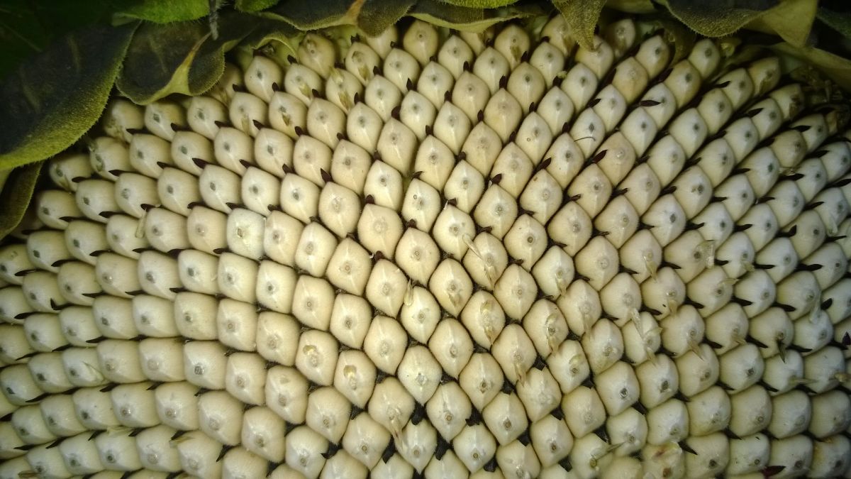
1.0 Phyllotaxis Spirals
The term phyllotaxis (from the Greek phullon ‘leaf,’ and taxis ‘arrangement) was coined around the 17th century by a naturalist called Charles Bonnet. Many notable botanists have explored the subject, such as Leonardo da Vinci, Johannes Kepler, and the Schimper brothers. In essence, it is the study of plant geometry – the various strategies plants use to grow, and spread, their fruit, leaves, petals, seeds, etc.
1.1 Rational Numbers
Let’s say that you’re a flower. As a flower, you want to give each of your seeds the greatest chance of success. This typically means giving them each as much room as possible to grow, and propagate.
Starting from a given center point, you have 360 degrees to choose from. The first seed can go anywhere and becomes your reference point for ‘0‘ degrees. To give your seeds plenty of room, the next one is placed on the opposite side, all the way at 180°. However the third seed comes back around another 180°, and is now touching the first, which is a total disaster (for the sake of the argument, plants lack sentience in this instance: they can’t make case-by-case decisions and must stick to one angle (the technical term is a ‘divergence angle‘)).

Next time you only go to 90° with your second seed, since you noticed free space on either side. This is great because you can place your third seed at 180°, and still have room for another seed at 270°. Bad news bears though, as you realise that all your subsequent seeds land in the same four locations. In fact, you quickly realise that any number that divides 360° evenly yields exactly that many ‘spokes.’


Note: This is technically true with numbers as high as 120, 180, or even 360(a spoke every 1°.) However the space between seeds in a spoke gradually becomes greater than the space between spokes themselves, leaving you with one big spiral instead.

1.2 Irrational Numbers
These ‘spokes’ are the result of the periodic nature of a circle. When defining an angle for this experiment, the more ‘rational’ it is, the poorer the spread will be (a number is rational if it can be expressed as the ratio of two integers). Naturally this implies that a number can be irrational.
Sal Khan has a great series of short videos going over the difference between the two [Link]. For our purposes, the important take-aways are:
-Between any two rational numbers, there is at least on irrational number.
–Irrational numbers go on and on forever, and never repeat.
You go back to being a flower.
Since you’ve just learned that an angle defined by a rational number gives you a lousy distribution, you decide to see what happens when you use an angle defined by an irrational number. Luckily for you, some of the most famous numbers in mathematics are irrational, like π (pi), √2 (Pythagoras’ constant), and e (Euler’s number). Dividing your circle by π (360°/3.14159…) leaves you with an angle of roughly 114.592°. Doing the same with √2 and e leave you with 254.558° and 132.437° respectively.

Great success. These angles are already doing a much better job of dispersing your seeds. It’s quite clear to you that √2 is doing a much better job than π, however the difference between √2 and e appears far more subtle. Perhaps expanding these sequences will accentuate the differences between them.

It’s not blatantly obvious, but √2 appears to be producing a slightly better spread. The next question you might ask yourself is then: is it possible to measure the difference between the them? How can you prove which one really is the best? What about Theodorus’, Bernstein’s, or Sierpiński’s constants? There are in fact an infinite amount of mathematical constants to choose from, most of which do not even have names.
1.3 Quantifiable irrationality
Numbers can either be rational or irrational. However some irrational numbers are actually more irrational than others. For example, π is technically irrational (it does go on and on forever), but it’s not exceptionally irrational. This is because it’s approximated quite well with fractions – it’s pretty close to 3+1⁄7 or 22⁄7. It’s also why if you look at the phyllotaxis pattern of π, you’ll find that there are 3 spirals that morph into 22 (I have no idea how or why this is. It’s pretty rad though).


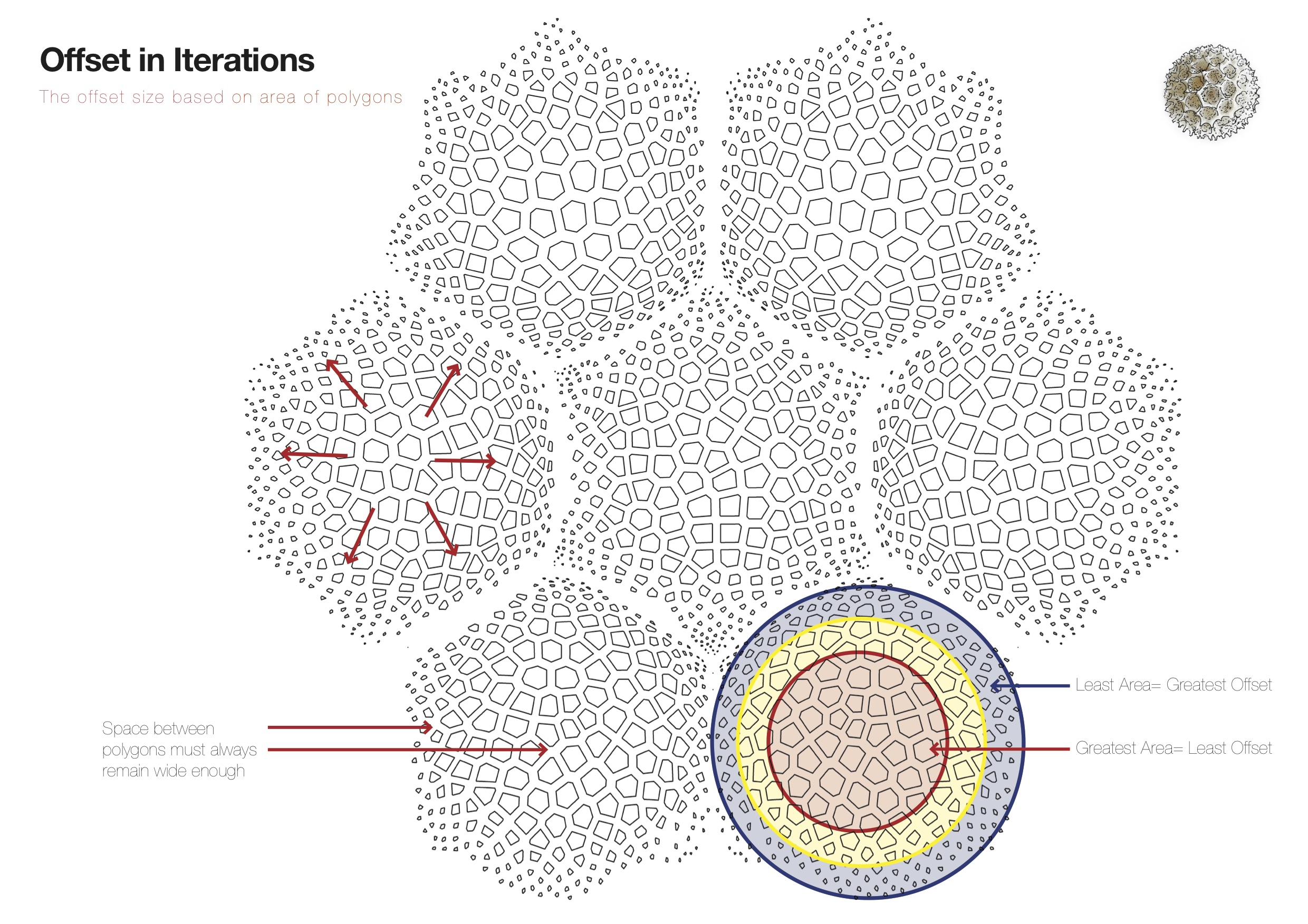
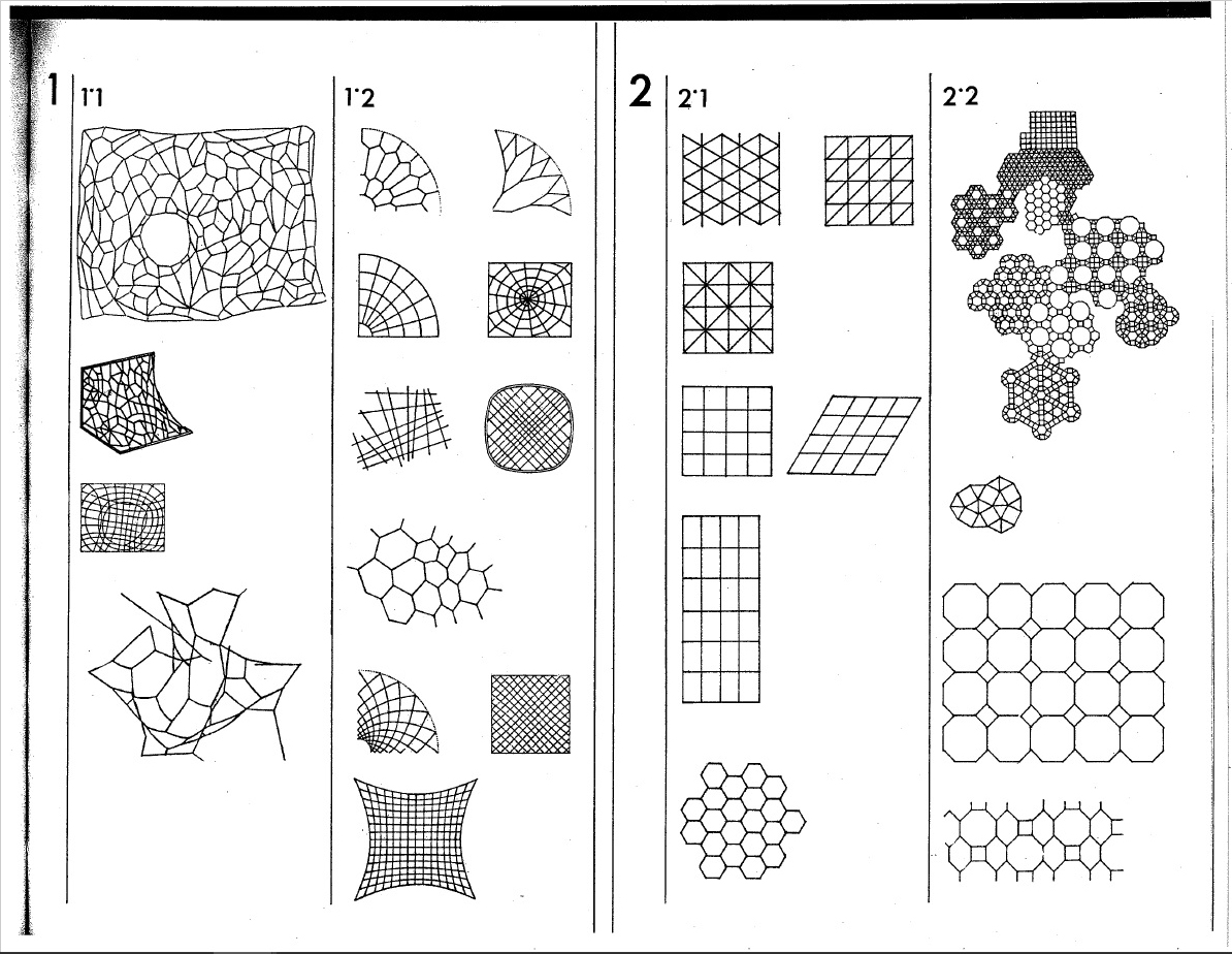
Generating a voronoi diagram with your phyllotaxis patterns is a pretty neat way of indicating exactly how much real estate each of your seeds is getting. Furthermore, you can colour code each cell based on proximity to nearest seed. In this case, purple means the nearest neighbour is quite close by, and orange/red means the closet neighbour is relatively far away.

Congratulations! You can now empirically prove that √2 is in fact more effective than e at spreading seeds (e‘s spread has more purple, blue, and cyan, as well as less yellow (meaning more seeds have less space)). But this begs the question: how then, can you find the most irrational number? Is there even such a thing?
You could just check every single angle between 0° and 360° to see what happens.
This first thing you (by which ‘you,’ I mean ‘I’) notice is: holy cats, that’s a lot of options to choose from; how the hell are you suppose to know where to start?
The second thing you notice is that the pattern is actually oscillating between spokes and spirals, which makes total sense! What you’re effectively seeing is every possible rational angle (in order), while hitting the irrational one in between. Unfortunately you’re still not closer to picking the most irrational one, and there are far too many to compare one by one.
1.4 Phi
Fortunately you don’t have to lose any sleep over this, because there is actually a number that has been mathematically proven to be the most irrational of all. This number is called phi (a.k.a. the Golden/Divine + Ratio/Mean/Proportion/Number/Section/Cut etc.), and is commonly written as Φ (uppercase), or φ (lowercase).
It is the most irrational number because it is the hardest to approximate with fractions. Any number can be represented in the form of something called a continued fraction. Rational numbers have finite continued fractions, whereas irrational numbers have ones that go on forever. You’ve already learned that π is not very irrational, as it’s value is approximated pretty well quite early on in its continued fraction (even if it does keep going forever). On the other hand, you can go far further in Φ‘s continued fraction and still be quite far from its true value.
Source:
Infinite fractions and the most irrational number: [Link]
The Golden Ratio (why it is so irrational): [Link]
Since you’re (by which ‘you’re,’ I mean I’m) a flower (by which ‘a flower,’ I mean ‘an architecture student’), and not a number theorist, it’s less important to you why it’s so irrational, and more so just that it is so. So then, you plot your seeds using Φ, which gives you an angle of roughly 137.5°.

It seems to you that this angle does a an excellent job of distributing seeds evenly. Seeds always seem to pop up in spaces left behind by old ones, while still leaving space for new ones.

Expanding the this pattern, as well as the generation of a voronoi diagram, further supports your observations. You could compare Φ‘s colour coded voronoi/proximity diagram with the one produced using √2, or any other irrational number. What you’d find is that Φ does do the better job of evenly spreading seeds. However √2 (among with many other irrational numbers) is still pretty good.
1.5 The Metallic Means & Other Constants
If you were to plot a range of angles, along with their respective voronoi/proximity diagrams, you can see there are plenty of irrational numbers that are comparable to Φ (even if the range is tiny). The following video plots a range of only 1.8°, but sees six decent candidates. If the remaining 358.2° are anything like this, then there could easily well over ten thousand irrational numbers to choose from.
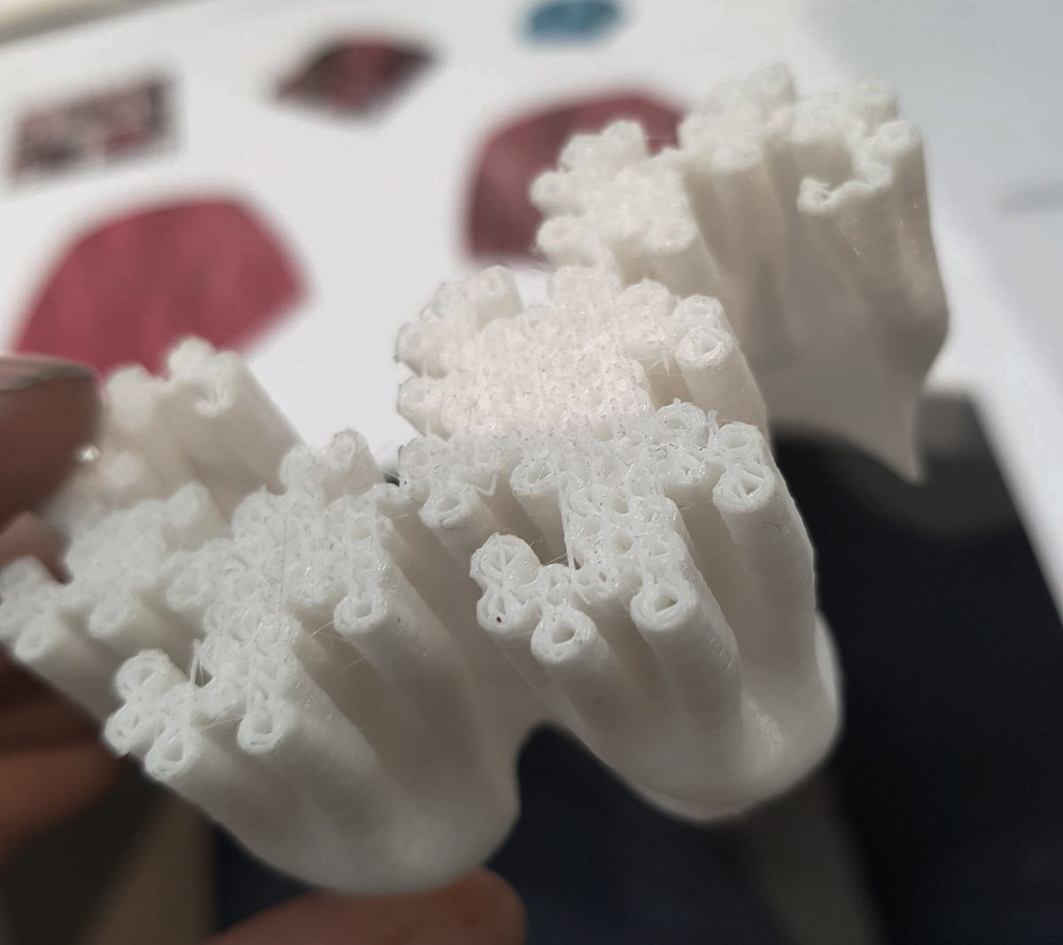
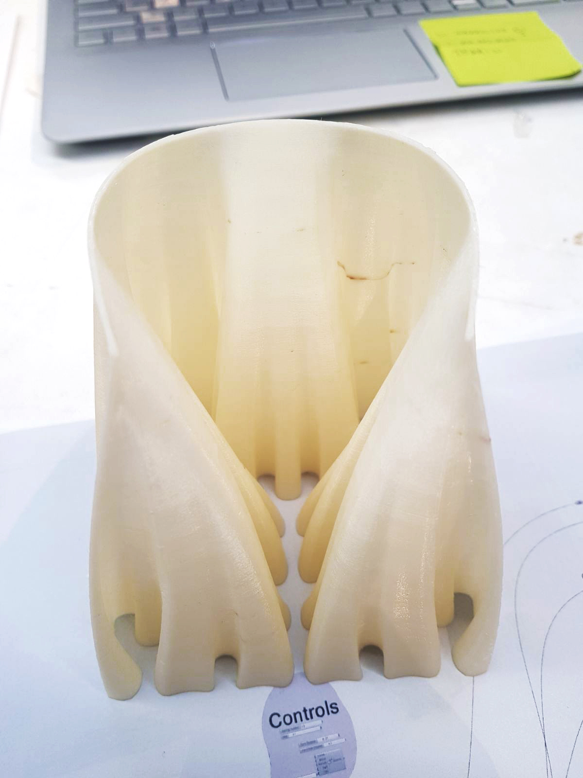
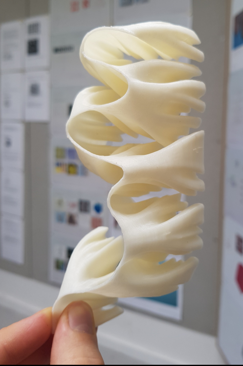
It’s worth noting that this is technically not how plants grow. Rather than being added to the outside, new seeds grow from the middle and push everything else outwards. This also happens to by why phyllotaxis is a radial expansion by nature. In many cases the same is true for the growth of leaves, petals, and more.
It’s often falsely claimed that the Φ shows up everywhere in nature. Yes, it can be found in lots of plants, and other facets of nature, but not as much as some people mi
ght have you believe. You’ve seen that there are countless irrational numbers that can define the growth of a plant in the form of spirals. What you might not know is that there is such as thing as the Silver Ratio, as well as the Bronze Ratio. The truth is that there’s actually a vast variety of logarithmic spirals that can be observed in nature.

Source:
The Silver Ratio & Metallic Means: [Link]
1.6 Why Spirals?
A huge variety of plants have been observed to exhibit spirals in their growth (~80% of the 250,000+ different species (some plants even grow leaves at 90° and 180° increments)). These patterns facilitate photosynthesis, give leaves maximum exposure to sunlight and rain, help moisture spiral efficiently towards roots, and or maximize exposure for insect pollination. These are just a few of the ways plants benefit from spiral geometry.
Some of these patterns may be physical phenomenons, defined by their surroundings, as well as various rules of growth. They may also be results of natural selection – of long series of genetic deviations that have stood the test of time. For most cases, the answer is likely a combination of these two things.
In some of the cases, you could make an compelling arrangement suggesting that these spirals don’t even exist. This quickly becomes a pretty deep philosophical question. If you put a series of points in a row, one by one, when does it become a line? How close do they have to be? How many do you have to have? The answer is kinda slippery, and subjective. A line is mathematically defined by an infinite sum of points, but the brain is pretty good at seeing patterns (even ones that don’t exist).
M.C. Escher said that we adore chaos because we love to produce order. Alain Badiou also said that mathematics is a rigorous aesthetic; it tells us nothing of real being, but forges a fiction of intelligible consistency.


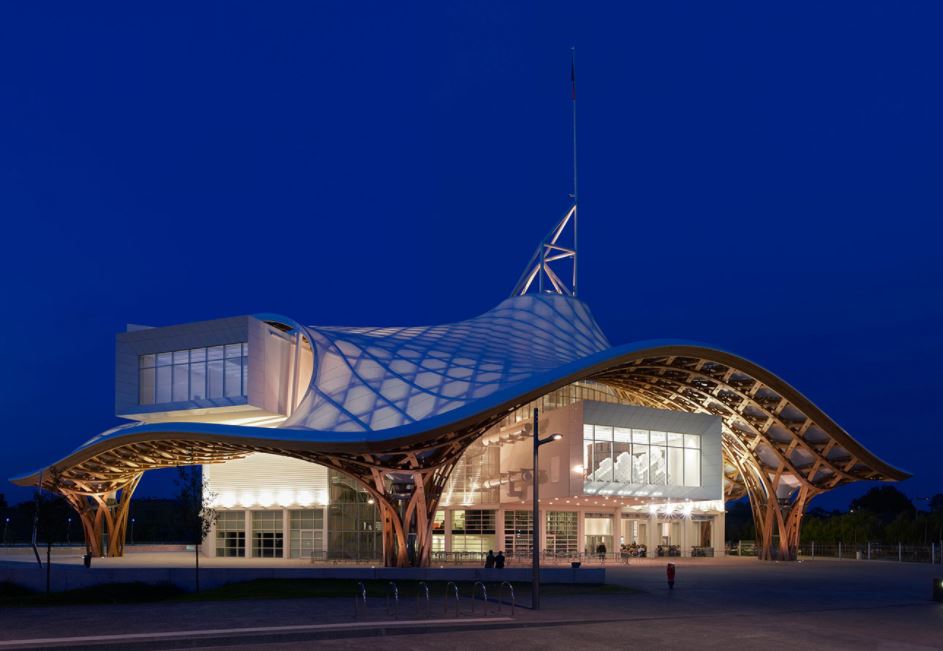


 Johann Wolfgang von Goethe says Architecture is frozen music. Albert Einstein believes the key to unlocking the universe is through the hidden geometry and mathematics. This design seeks to unlock the geometry of Sound making sound visible through 3-dimensional volume and lights.


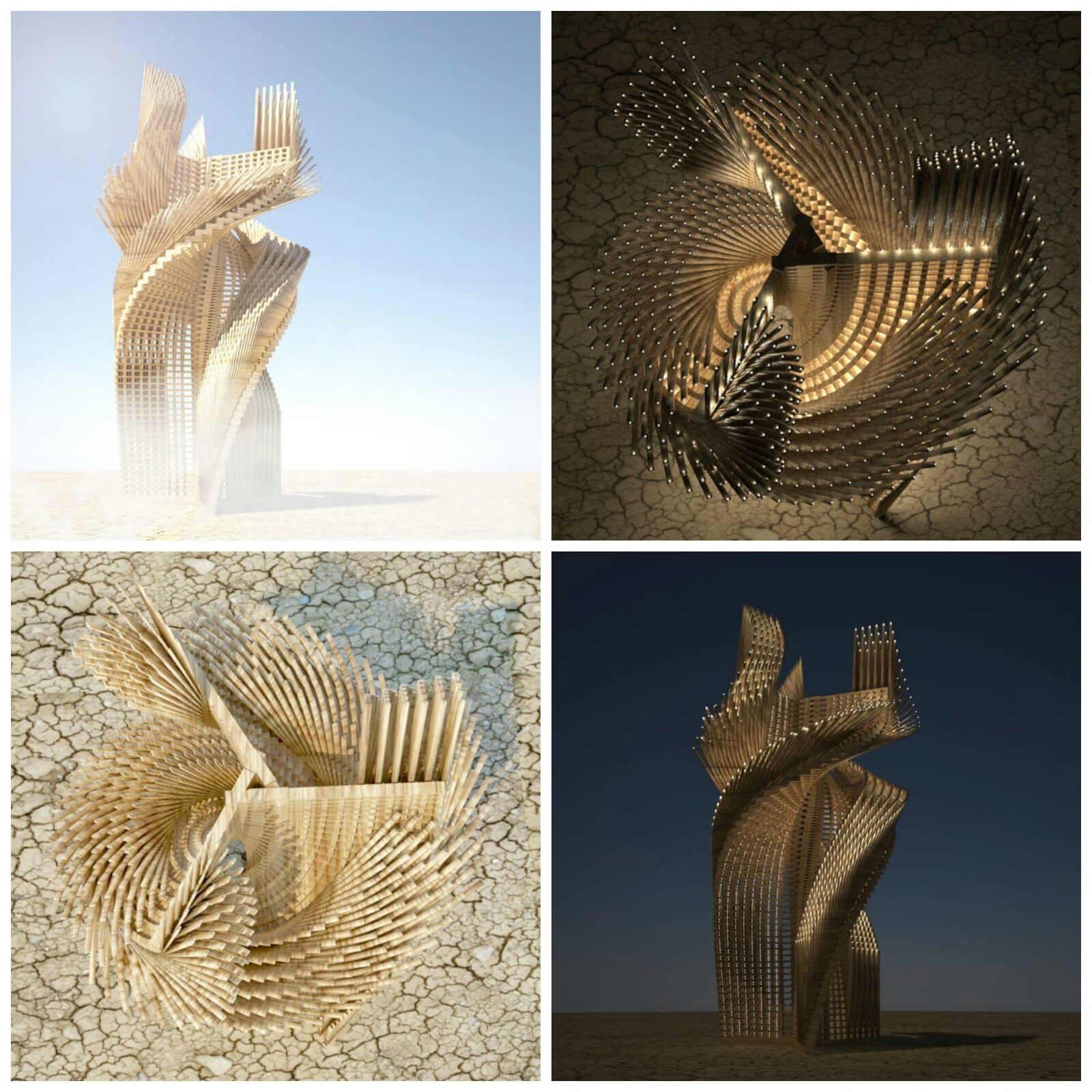


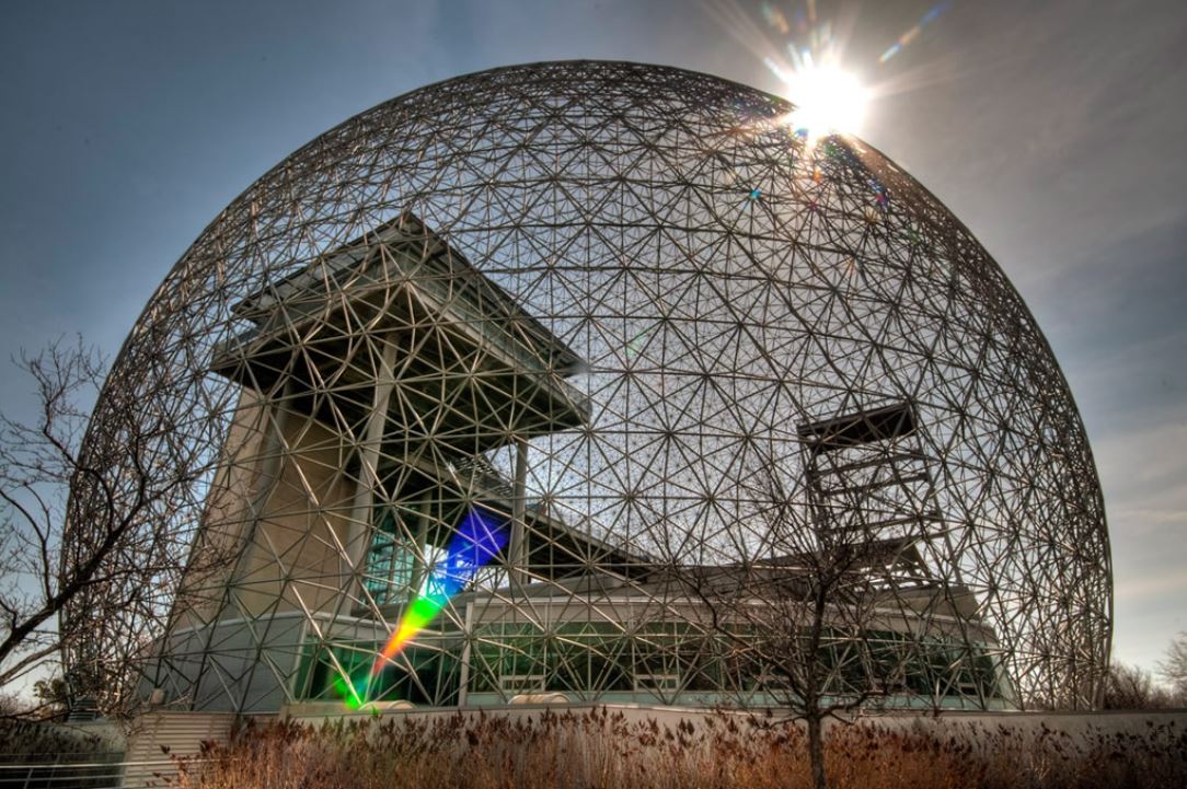
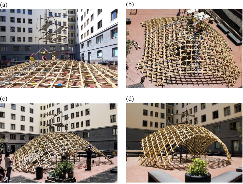
 The form of the structure is based on the octahedron, which is a Platonic solid composed of eight equilateral triangles; four of which meet at each vertex. One of the eight triangles acts as a base for the structure. This results in one edge creating a small cantilever, whilst the counter edge can be anchored to the ground. As previously studied by Buckminster Fuller, the geometry of an octahedron is particularly good at forming space frames with a strong cantilevers.


![White Royal [Pratapa deva relata] HuDie's Microphotography](https://wewanttolearn.files.wordpress.com/2015/11/the-square-egg.jpg)


 A truncated icosahedron for a frame, the opposite of a football. Instead of panels pushed out, they are pulled in.