A deployable structure includes an enclosed mechanical linkage capable of transformation between expanded and collapsed configurations while maintaining its shape.
These types of structures have the advantage of creating versatile, modulated spaces, with easy and fast assembly which generate benefits such as adaptability, flexibility and space transformation.
Charles Hoberman pioneered a type of deployable structure based on curved scissor pairs as seen in his Hoberman sphere. The unfolding structure resembles an expanding geodesic sphere which can reach a size up to five times larger than the initial one. It consists of six loop assemblies (or great circles), each made of 60 elements which fold and unfold in a scissor-like motion. 
Hoberman Sphere by Charles Hoberman
A loop assembly is formed of at least three scissors-pairs, at least two of the pairs comprising two identical rigid angulated strut elements, each having a central and two terminal pivot points with centres which do not lie in a straight line, each strut being pivotally joined to the other of its pair by their central pivot points. The terminal pivot points of each of the scissors-pairs are pivotally joined to the terminal pivot points of the adjacent pair such that both scissors-pairs lie essentially in the same plane.
Regular curved scissor-pairs in motion
When this loop is folded and unfolded certain critical angles are constant and unchanging. These unchanging angles allow for the overall geometry of structure to remain constant as it expands or collapses.
Regular and irregular curved scissor-pairs in motion
The above diagrams show a closed loop-assembly of irregular scissors pairs where each scissors-pair is pivotally joined by its two pairs of terminal pivot points to the terminal pivot points of its two adjacent scissors-pairs. This loop-assembly is an approximation of a polygon in the sense that the distances between adjacent central pivot points are equal to the corresponding lengths of the sides of the polygon. Further, the angles between the lines joining adjacent central pivot points with other similarly formed lines in the assembly are equal to the corresponding angles in the polygon.
The beams forming scissor-pairs can be of almost any shape, providing that the three connection points form a triangle. The angle of the apex would dictate the number of scissor-pairs that can be linked together to form a closed loop.
Scissor-pairs of varying morphologies
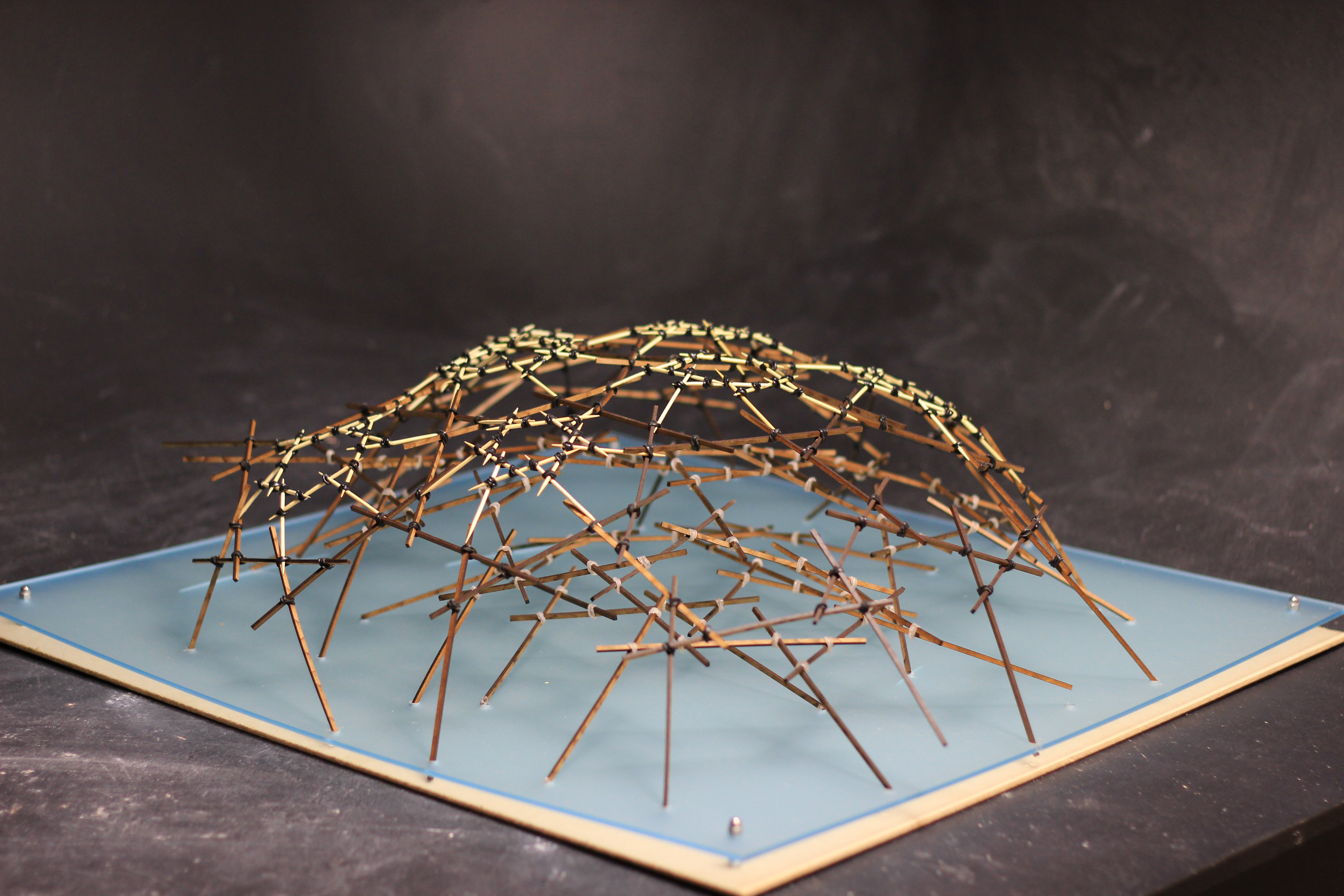
My physical experiments started with materials that would allow a degree of bending and torsion in order to test the limits of the system. Using polypropylene for the angular beams and metal screws for the joints, I created these playful models that bend as they expand and contract.
Later I started using MDF for the beams as well as joints and noticed that a degree of bending was present in the expanded state of the larger circle.
After using curved scissor pairs of the same angle to form closed linkages, I decided to combine two types of scissors and vary the proportion between the elements to achieve a loop which would offer the highest ratio between the expanded and contracted state.
900 curved scissors loops

900 curved scissors with linear scissors loops
The above diagrams show a combination of 900 curved scissors with linear (1800) scissors to form rectangles that expand and contract. The length of the 900 beam was gradually increased and by measuring the diagonals of the most expanded and most contracted forms, I obtained the following ratios for the three rectangles:
R1 = 0.87
R2 = 0.67
R3 = 0.64
By keeping the curved scissor with the best ratio, I created three more rectangles, this time by varying the length of the linear beam. The following ratios were obtained:
R1 = 0.64
R2 = 0.59
R3 = 0.67
900 curved scissors with linear scissors loops
I then took the linkage with the best ratio of 0.59 and rotated it 900 to form a cube which expands and contracts.

Combined linkage cubes
The change of state from open to closed is visually attractive and could have the potential of creating spaces that are transitional. If more linear scissors are placed between the 900 scissors, a better contraction ratio is obtained.
Combined linkage cubes with two linear scissors
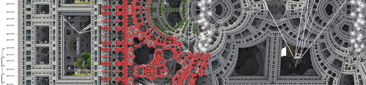
 London churches with a Holy Door
 ‘Rose’ configurations
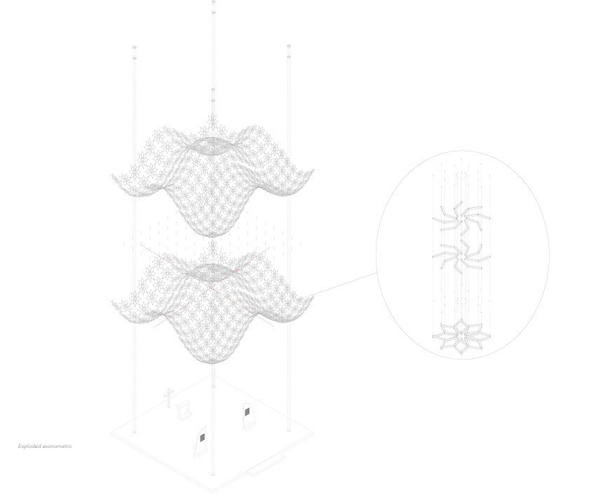


 Vacation city

