
Dutch Invertuals – ‘Cohesion’
Moiré patterns are superimposed secondary patterns created when two static surface patterns are overlaid one on top of the other. By displacing or rotating one or both patterns a new visual pattern becomes visible separate to the geometry of the first two. This moiré effect is created in the eye of the viewer, disparate from the shapes formed by the individual patterns themselves.

A moiré pattern generated by overlapping two identical patterns of concentric circles
Associated mathematical formulas can be used to determine the size and spacing of inferred moiré patterns from a series of regularly spaced overlaid patterns. The beauty of the moiré effect is the illusion of movement created through completely static overlays. This forms a naturally interactive experience for the participant, giving over control to the superimposed pattern through visual movement and rotation.
Physical Moiré experiments
The video above illustrates the moiré effect in two dimensions by overlaying static linear and concentric patterns, printed on acetate, and manipulating their motion and rotation in order to create a new visual pattern.

Concentric and Linear patterns, printed on acetate overlays
This effect is not restricted to two dimensional patterns but can also be applied in three dimensions. These spatial patterns then utilise the motion of the viewer in order to manipulate the moiré effect. The video below illustrates how three dimensional sculpted elements, set on separate spatial planes can form a visual pattern and take advantage of simple motions by the viewer.
Scale model of the facade for Brisbane Girls School Creative Learning Centre – M3 Architects
The two primary resultant effects from the physical experiment above illustrate the potential of moiré to create alternate visual patterns and to generate the illusion of movement. These were then applied digitally to create an animation that controls these aspects to create a recognisable representation of motion to the viewer, as opposed to an abstract pattern.
Digital testing of the moiré effect in animation
The above digital animation illustrates the rotational movement of a circle through the movement of a linear overlay, created with the two static images below:
 The linear moiré overlay
The moiré underlay creating the circular motion
This moiré underlay is created through a series of rules defined by the size of the overlay and the direction, factor and type of movement (linear or rotational). The diagram below explores the rules associated with this specific type of moiré animation.

Rules for defining a moiré ‘underlay’ for linear animation
Whilst primarily a visual effect it is the ability to translate spatially which gives the moiré effect the potential to be applied in a design context, particularly given it’s interactive nature and the reliance on the involvement of participants in order to reveal it’s true beauty.
The video below takes this concept to the extreme, exploring the effects of imagining matter as nothing more than multi-dimensional moiré patterns……
Moiré – Julias Horsthuis
Updated Research:
Video illustrating various physical moiré experiments

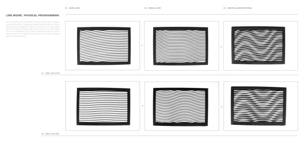
Rules for defining moiré patterns in linear gratings

Mathematical rules for defining moiré patterns of rotation

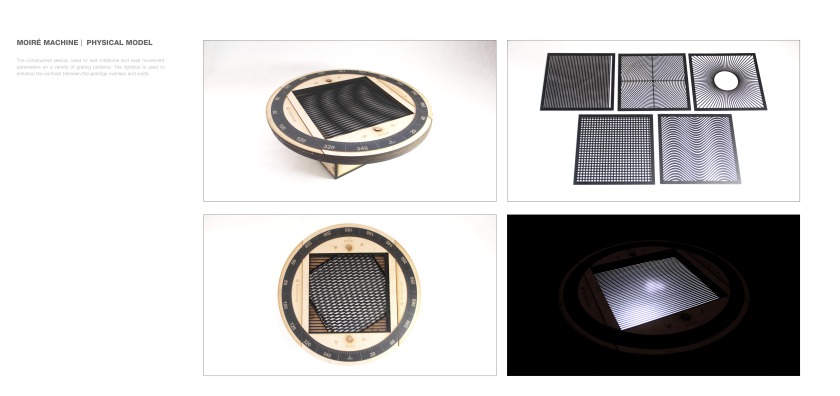
Physical model for experimenting with moiré rotation patterns


Results from the physical model using sin curves & square gratings
Moiré patterns can be ‘programmed’ using a certain mathematical formula. If two variables are known; the base layer and the desired moiré pattern (in this instance a sin curve) the resultant reveal layer can be determined, allowing moiré patterns to be programmed to any shape.

Digital tests and physical proofs of programming moiré
Moiré patterns work in both ‘positive’ and ‘negative’ constructions. Positive moiré can be classed as additive, constructing patterns consisting of lines to create the effect. Negative moiré conversely removes elements of material (in this instance circles from card) to create patterns when held at a distance. The bottom row of images shows the most successful variables for discerning negative moiré patterns.


Negative moiré, set-up & physical experiment
The above experiment was digitally reproduced, modelling its negative space in order to understand how the variables of distance affect the reception of pattern.

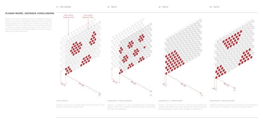
Digital experiments with distance variables
In order to move from the plane into a spatial exploration of the moiré effect, sin curve gratings were mapped onto the faces of a cube, at varied rotations. The effect is a spatial understanding of moiré patterns when the various faces of the cube overlap. The moiré effect can be created by two distinct methods; a movement by the user, distorting the areas of overlap and the movement of the cube itself, visually shifting patterns.

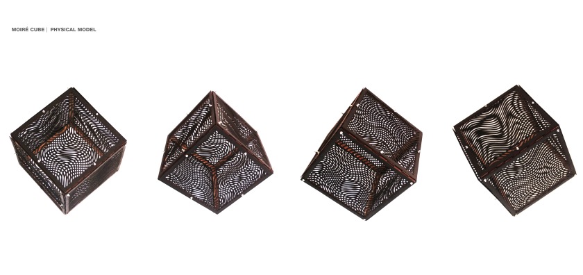
Physical model exploring moiré patterns in three dimensions


