


This project involves the conception and design of a new way of mapping constellations, based on subdivision processes like Stellation. It explores how subdivision can define and embellish architectural design with an elaborate system of fractals based on mathematics and complex algorithms.

An abstracted form of galaxy is used as an input form to the subdivision process called Stellation. In geometry, meaning the process of extending a polytope in n dimensions to form a new figure. Starting with an original figure, the process extends specific elements such as its edges or face planes, usually in a symmetrical way, until they meet each other again to form the closed boundary of a new figure.

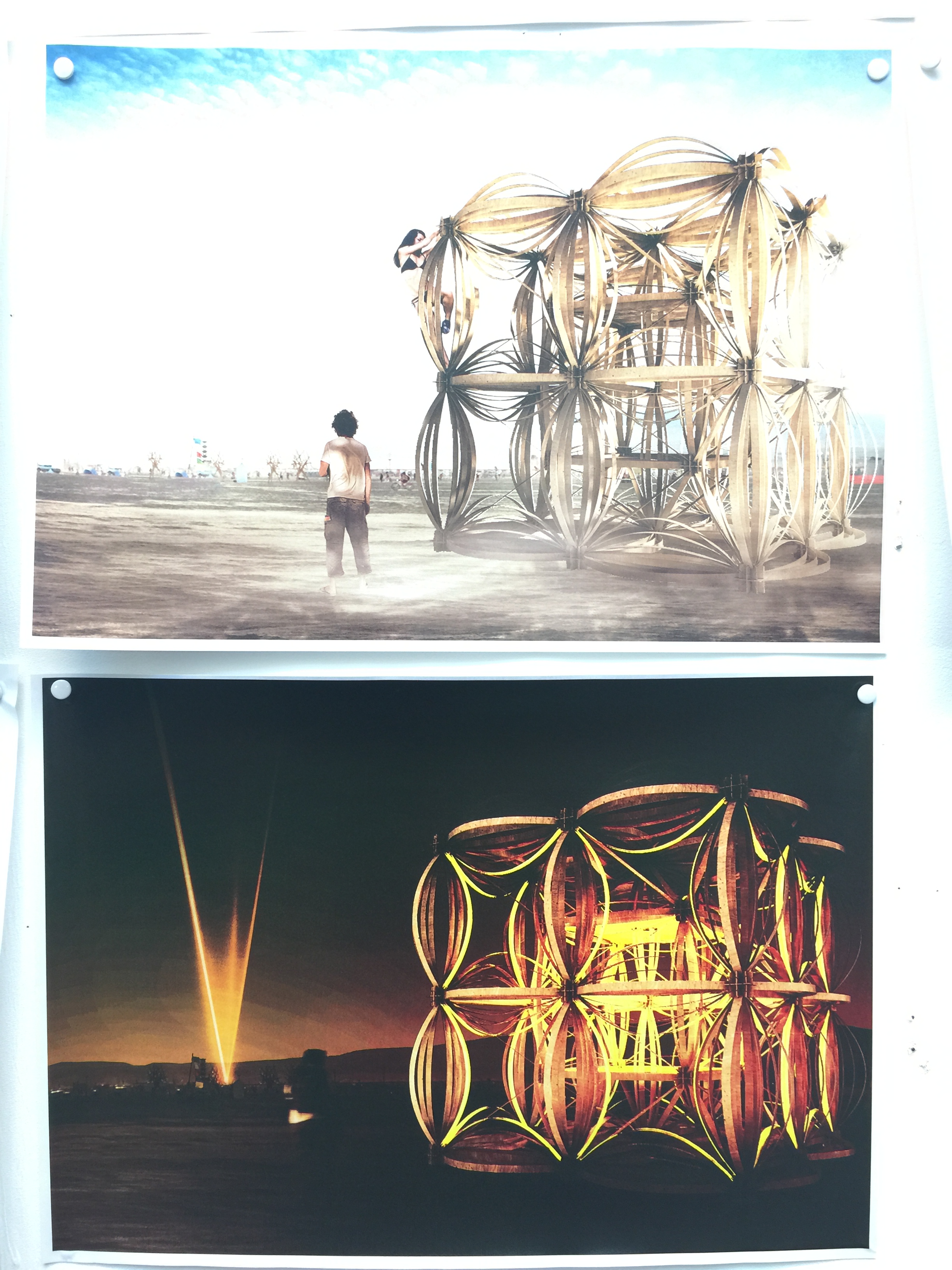
The material used for this installation will be timber sheets of 1/3 of an inch thickness that will be laser-cut.The panels will be connected to each other with standard connection elements which have already been tested structurally based on an origami structure.
The lighting of the installation will consist on LED strips that will light with burners interactions.

Although stars in constellations appear near each other in the sky, they usually lie at a variety of distances away from the observer. Since stars also travel along their own orbits through the Milky Way, the constellation outlines change slowly over time and through perspective.
There are 88 constellations set at the moment, but I would like to prove that there are infinite amount of stars that have infinite amount of connections with each other.The installation will show you all the possible connections between this stars, but will never rule which connection is the one you need to make.

I would like burners to choose their own stars and draw their own constellations. Any constellation that they can possibly imagine from their one and only perspective, using coloured lights that react to their touch.
The end result will have thousands of different geometries/constellations that will have a meaning for each one of the burners and together will create a new meaningful lighted galaxy full of stars.

On a clear night, away from artificial light, it’s possible to see over 5000 stars with the naked eye. These appear to orbit the Earth in a fixed pattern, as if they are attached to a giant sphere that makes one revolution a day.This stars though are organised in Constellations.
The word “constellation” seems to come from the Late Latin term cōnstellātiō, which can be translated as “set of stars”. The relationship between this sets of stars has been drawn by the perspective of the human eye.

“Omnis Stellae” is a manifestation of the existence of different perspectives. For me, there is great value in recognising different perspectives in life, because nothing is really Black and White, everything relates to the point of view and whose point of view and background that is.
As a fractal geometry this installation embodies an endless number of stars that each person can connect and imagine endless geometries, that will only make sense from their own perspective. The stellated geometry will show you all the possible connections but will never impose any.

“Omnis Stellae” is about creating your own constellations and sharing them with the rest of the burners, is about sharing your own perspective of the galaxy and create some meaningful geometries that might not mean anything to other people but would mean the world to you.

The grand finale is if it could become the physical illustration of all the perspectives of the participants at Burning Man 2018 shown as one.
With Love,
Maya
A hyperbolic paraboloid is an infinite surface in three dimensions with both hyperbolic and parabolic cross-sections. A playful and intuitive way of visualising and parameterising this concept can be achieved via the implementation of origami folding techniques.
The images below show how to create and tile a basic hyperbolic parabola with origami. Once fully formed, the result is flexible and malleable along its two axes.


This playfulness only increases as additional sides are added to the initial parametric shape. This, in turn directly correlates with the increase of the number of axes along which the paraboloid is able to form. For example, a hexagonal initial sheet with six sides, will also have six axes.


Octagonal and decagonal paraboloids are particularly enjoyable to create and play with.
When deconstructed, a decagonal paraboloid is comprised entirely of a series of ever diminishing, 72 degree trapezoids, that when tiled next to one another, come together to comprise individual components of one, larger trapezoid, or wedge. When tiled and secured along its long edge, a decagon is formed, and once folded, a hyperbolic paraboloid is possible.
It is through research and testing with digital fabrication how best to form and therefore scale this wedge component that a successful, parametric and human scale origami form might be accomplished.


The images below are further tests in a failed attempt at forming a larger, scalable hexagonal paraboloid. Previously, flexible material such as paper and polypropylene had been used to successfully form basic, octagonal and decagonal paraboloids. However, in this test, 4mm ply was used, and has proved to be most inflexible. Thusly, it is unable to bend universally along each of the six axes. Further testing is required.


Some images of our final cross-crit of the year! Our students presented their Brief03:FutureCities. Have a look at how the next generation of architects envision the future of our cities.
Thank you to Andrei Jipa, Kester Rattenbury and Lindsay Bremner. Final sprint to the portfolio submission and end of year!


The Atlantic Forest in southern Brazil has long been viewed as a vast quilt of rain forest interspersed by small river outposts. The surging population growth has seen these remote settlements transform this ancient rural vision to an expansive city scale. Cidade de Árvores (City of Trees) envisions an environment where both the city’s infrastructure and its inhabitants maintain a symbiotic relationship with the surrounding natural environment. Built entirely from locally grown timber, the Cidade de Árvores exists as a network of steam bent beams, joined to form a structural space frame. Like the forest, the frame is allowed to grow and develop organically over time with inhabitants adding to structure to meet their requirements. The city is powered through the use of micro wind turbine electricity generation which manifests as a series of towers scattered throughout the forest. For the city and the environment to function in harmony, the city access routes manifest as elevated walkways around large courtyards, allowing light to penetrate to the forest floor.


Some joyous proposals for both Burning Man and Buro Happold’s London office at yesterdays crit, the first of the year.
Our guest critics were Andrew Best, James Solly, Andrei Jipa, Harry Charringdon and Ben Stringer. Thank you all for your inspiring comments and tireless enthusiasm throughout the day.
Here are some images of the exciting work coming out of the studio this year, more to come 🙂


We are approaching the first “crit” of the term and our students are already proposing joyful projects for the Burning Man festival and Buro Happold’s newly refurbished HQ on Newman Street. The talented photographer NK Guy (http://nkguy.com/ and http://burningcam.com/) gave an excellent evening lecture at our campus to inspire our students and for the release of the book “The Art of Burning Man” (Taschen) which will feature some of our studio’s work. Here are couple images of the student’s project and of our buzzing DS10 space (pictures by Toby Burgess):


I have been researching Miura pattern origami as a structural solution for rapidly deployable structures. Miura ori are interesting as structures due to their ability to develop from a flat surface to a 3D form, and become fully rigid, with no degrees of freedom, once constrained at certain points.  Physical and digital experiments with Miura Ori have taught me that certain topographies can be generated by developing a modified Miura pattern. With the help of Tomohiro Tachi’s excellent research on the subject of curved Miura ori, including his Freeform Origami simulator (http://www.tsg.ne.jp/TT/index.html) I have learned that Miura ori surfaces that curve in the X and Y axes can be generated by modifying the tessellating components, however these modifications require some flexibility in the material, or looseness of the hinges.
  As a system for a rapidly deployable structure, I am most interested in the potential for the modified Miura ori to work as a structure built with cheap, readily available sheet materials which are generally planar, so I will continue to develop this system as a rigid panel system with loose hinges that can be tightened after the structure is deployed.
  In order to test the crease pattern’s ability to form a curved surface, I have defined a component within the Miura pattern that can tessellate with itself. The radius of this component’s developed surface is measured as it is gradually altered.
With the objective being to develop a system for the construction of a rapidly deployable structure, I have also been interested in understanding the Miura ori’s characteristics as it is developed from flat. Physical and digital tests were performed to determine the system’s willingness to take on a curve as its crease angles decrease from flat sheet to fully developed. I found the tightest radius was achieved rapidly as the sheet was folded, with the radius angle reaching a plateau. This is interesting from the perspective of one with the desire to create a structure that has a predictable surface topography, as well as from a material optimisation standpoint; the target topography can be achieved without the wasteful deep creases of an almost fully developed Miura ori.  With the learnings of the modified Miura ori tests in mind, a simple loose hinged cylinder is simulated. As the pattern returns on itself and is fastened, the degrees of freedom are removed and the structure is fully rigid.
  A physical model of the system was constructed with rigidly planar MDF panels and fabric hinges. The hinges were flexible enough to allow the hinge movement necessary in developing this particular modified Miura ori, however some of the panels’ corners peeled away from the fabric backing as the system was developed from flat. A subsequent test will seek to refine this hinge detail, with a view to creating a scalable construction detail that will allow sufficient flexibility during folding, as well as strength once in final position.
John Konings
j.e.konings@gmail.com
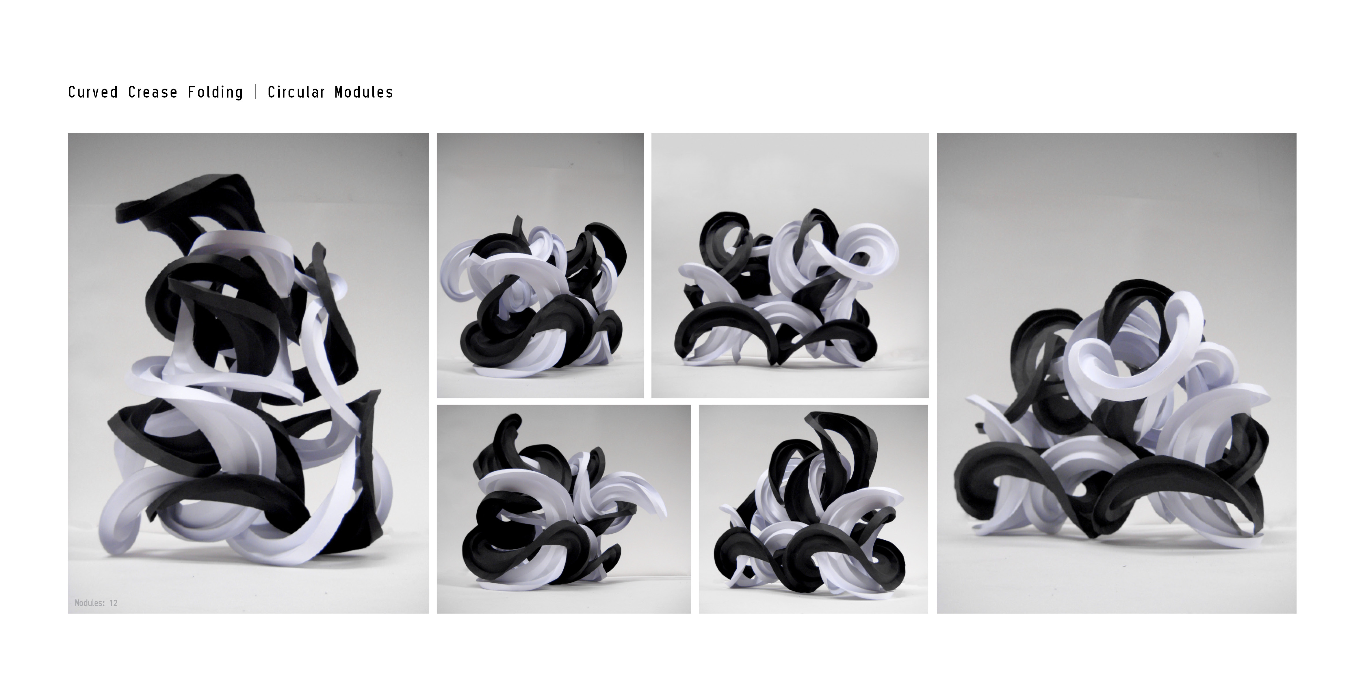
The history of curved crease folding goes back to as early as the Bauhaus, where a student had scored circular creases onto a paper in order to study its materiality. When a circular surface is folded along concentric rings, the resultant form bends on itself and forms a paraboloid in order to make up for the loss in circumference. Initial investigation involved the replication of such system and multiplying the modules which are then interlocked into each other to create various origami sculptures.

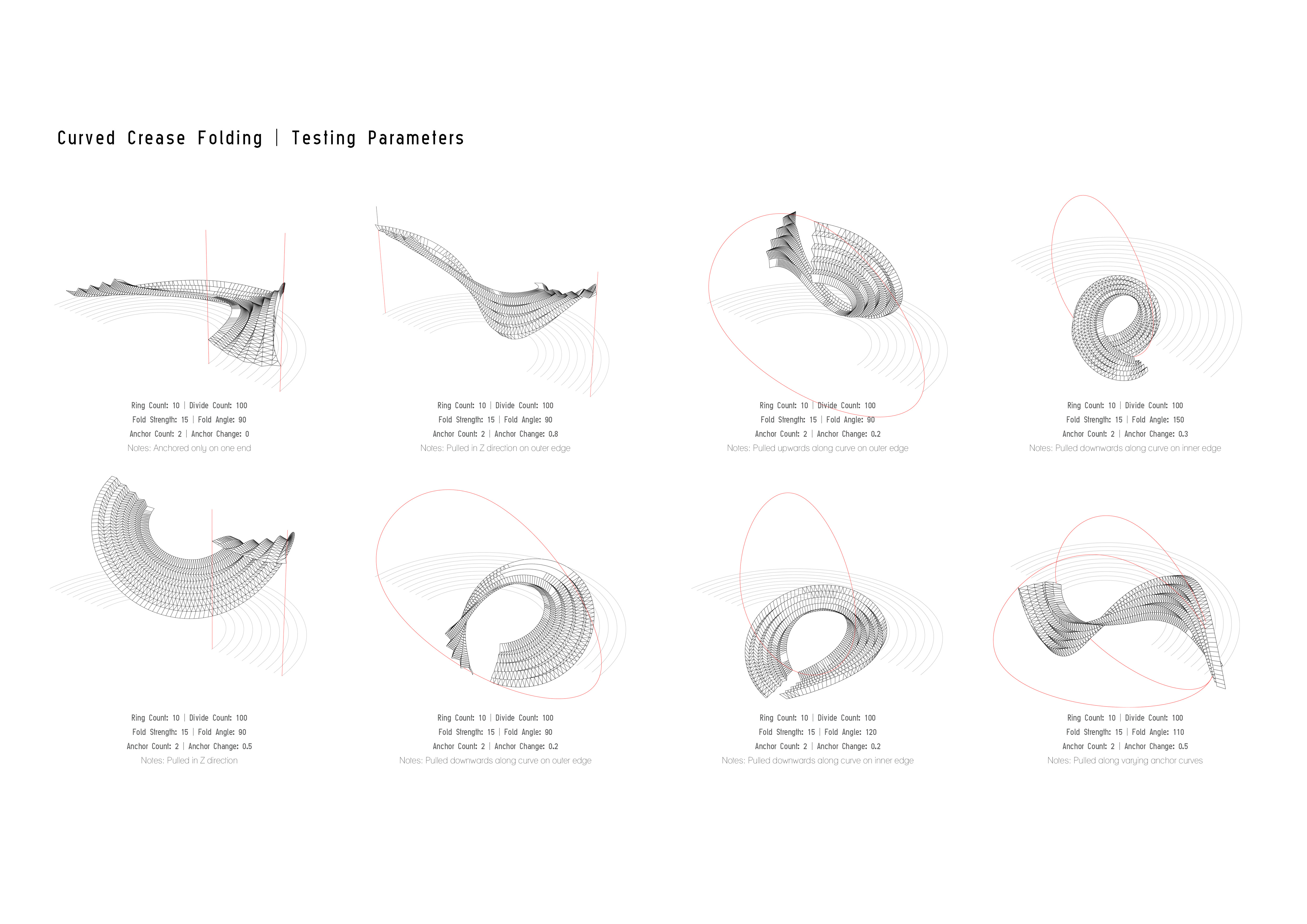
The system is then digitally simulated in order to extract the parameters which may affect the resultant geometry of the surface. With a combination of Kangaroo Physics, Hinge Forces and Springs, the digital simulation is created which allows anchor points to be placed, thus dragging for surface into various forms. Tests are carried out on different surfaces, including a closed circle of equal concentric rings, a closed circle of increasing concentric rings as well as an open circular strip with concentric rings. With an increasing fold angle, the bend angle increases.


Upon cutting the closed circle, the surface becomes an open ended circular strip. The constraints that follow a closed surface no longer presents itself, thus allowing the strip to bend freely – although the principles of the system still applies. With increasing fold angles, the strip bends at greater angle. Having this revelation, different open ended strips are then tested against different parameters to extract the system further.


In parallel to the research of curved crease folding is the investigation into the probability of transferring the system onto a more rigid, larger material, such as plywood. Here lattice hinge / kerf folds are employed, allowing the plywood to bend in a similar manner to card and paper. The final patterns for the hinges are a result of rigorous testing through trial and error. By repeating the modules we begin to see that, due to the folds, plywood can be as flexible as card.


First developed in 1979 by Dániel Erdély the Spidron is created by recursively dividing a 2-dimensional hexagon into triangles, forming a pattern that consists of one equilateral followed by one isosceles triangle. The resulting form is of six Spidron legs that, when folded along their edges, deform to create a 3-dimensional Spidron.


Initial investigations into the Spidron system using paper resulted in irregular shapes that could not be predicted, and therefore replicated precisely. Progressing onto using rigid materials allowed the system to be broken down into six components, removing unnecessary triangulated fold lines, and developing latch folded Spidron that is precisely the same as that formed parametrically.


This relationship between parametric and physical tests of component based Spidrons in both regular and irregular hexagons, as well as various other equal-sided shapes, has enabled the development of large scale models concluding thus far in a 1:2 scale version being built which will continue to be developed as a pavilion for submission to the Burning Man festival.

In parallel there has been an investigation into the system at a smaller scale allowing for the Spidron nest to be made as one component. In order to achieve the 3-dimensional Spidron form lattice hinges, also known as kerf folds, have been employed. Rigorous testing into the best cutting pattern have resulted in a straight line cutting pattern that allows for bending on multiple axis at once.


Developing this smaller scale system for submission to Buro Happold the intention is to create an arrayed system that is a conglomeration of both regular and irregular spidrons with varying depths and apertures that are able to integrate various display models etc. within.
We just finished Brief01:System/Sci-Fi and starting Brief02:Buro/Burn – Here are couple pictures of our last tutorials by Toby Burgess. Students will be uploading their systems on Monday on this blog!