S(l)OSH Pop-Up – Spa of Algorithmic Knowledge and Mud-

Big Sheets-6

Project Summary

S(l)OSH (standing for ‘ slosh= to move through mud’) is a new Pop-Up Spa situated in Hackney Road, in East London. It is designed as an interactive relaxation area to be experienced through exploring and reflecting within a cavernous space, surrounded by mysterious voids, while soaking in a healing mud tub. S(l)OSH represents a new concept of fun mud house, that tells a different side of the wellness story.

The Spa aims to promote the cleaning and health rituals around the world and invite the users to become aware of the areas in need of healthy kickstarts. The new concept started from the idea that spas and relaxation areas are generally luxurious places to relax and heal and sometimes they are too expensive for the general citizen. S(l)OSH wants to bring healthy hedonism to the city while boosting urban areas that need a little support, while making the cleaning and health rituals accessible and fun to everyone.

Big Sheets-3Big Sheets-5

Philosophy

Bathhouses, spas and saunas have long been part of cleaning and health rituals around the world. Mud baths have existed for thousands of years, and can be found now in high-end spas in many countries of the world. Mud wraps are spa treatments where the skin is covered in mud for a shorter or longer period. The mud causes sweating, and proponents claim that mud baths can slim and tone the body, hydrate or firm the skin, or relax and soothe the muscles. It is alleged that some mud baths are able to relieve tired and aching joints, ease inflammation, or help to “flush out toxins” through sweating.
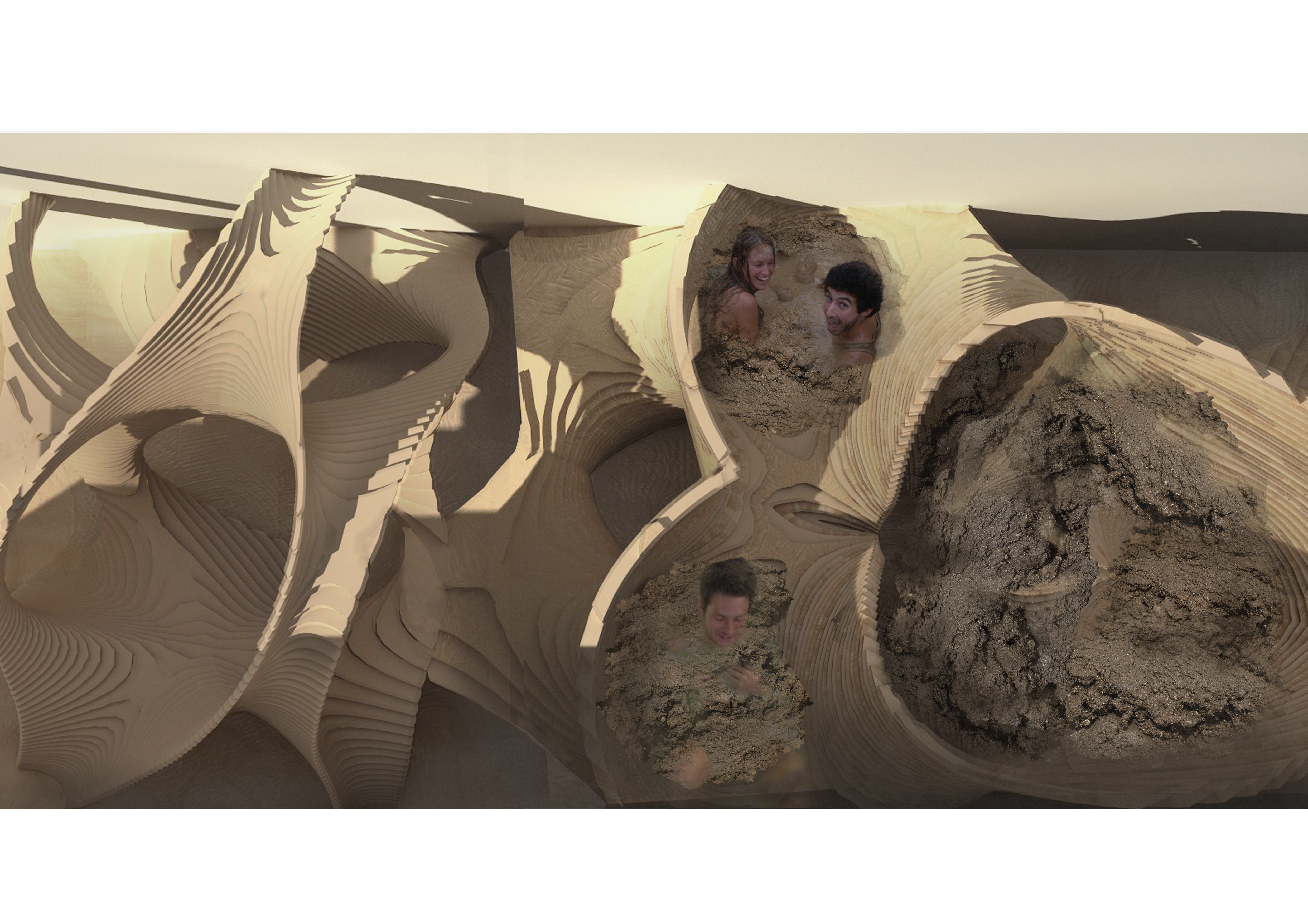
2aOpportunity

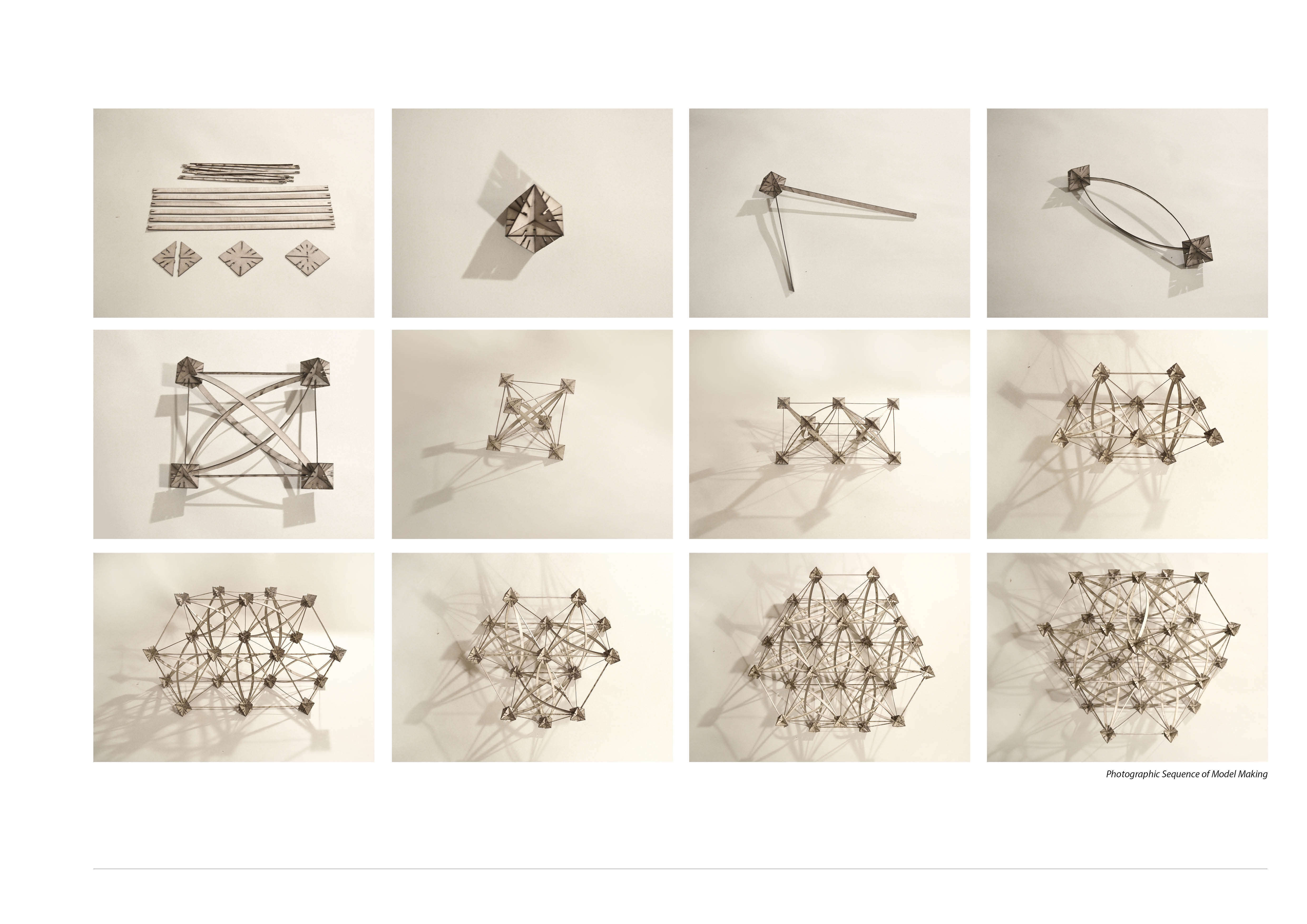
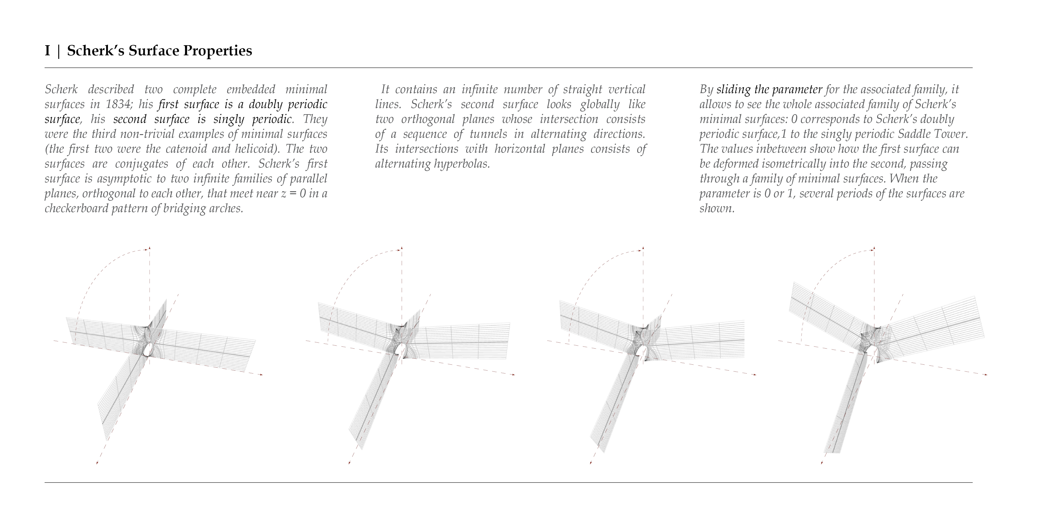
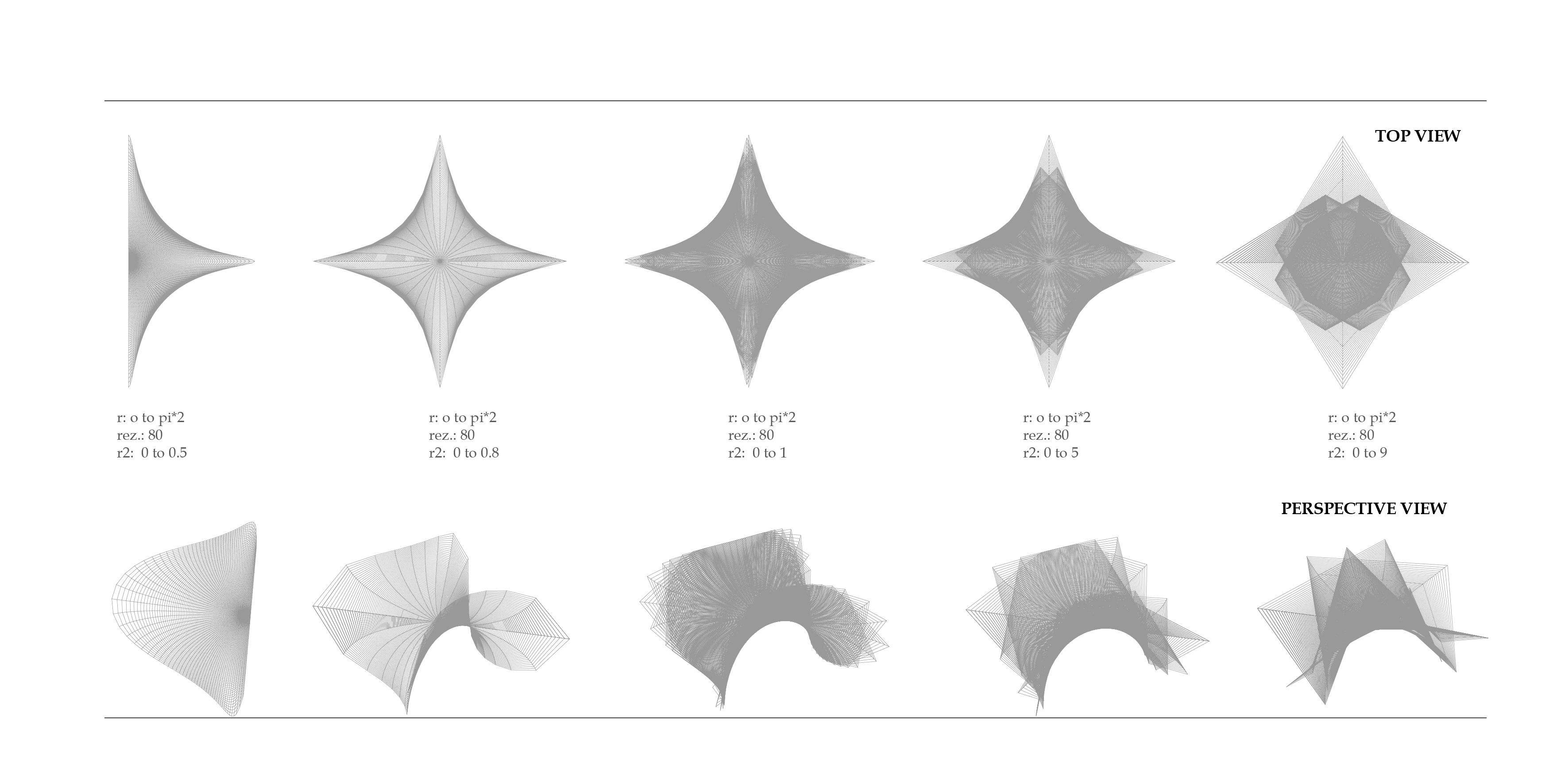
The design is composed of layers of horizontal wooden planks that follow the mathematical formula of a Scherk’s Minimal Surface geometry of a continuous surface, placed in and around a shipping container. The Spa has been designed after several form manipulation and shape iterations of the initial system, followed by massing of standard bath tubs in a tight space. The proposal stands somewhere between the realms of both sculpture and architecture – a spatial construct where movement through will encourage intimate social interaction, and a full emerge into the relaxation experience.

Big Sheets-4

Physical Description

Visually, the main part of the Spa is composed of three main areas: the reception, the mud baths and the outdoor pools. The spas includes hot mud tubes, cold water plunges, a changing area, shower and relaxation platforms. The structure will be built from layers of horizontal CNC cut wooden planks stacked on top of each other and fixed together. Internally, the bathtubes will have a smooth concrete walls to hold the liquid and make the stay more pleasant for the sitting. Despite being designed to fit in one or two containers, the spa can expand even outdoors and other spaces.

Brief 3 - S(l)OSH SPA (FINAL)Brief 3 - S(l)OSH SPA (FINAL)2 Brief 3 - S(l)OSH SPA (FINAL)3 Brief 3 - S(l)OSH SPA (FINAL)4 Brief 3 - S(l)OSH SPA (FINAL)5 Brief 3 - S(l)OSH SPA (FINAL)6


Bending Lattice System

My initial studies stemmed from researching into Stellation. This, in simple terms, is the process of extending  polygon in two dimensions, polyhedron in three dimensions, or, in general, a polytope in n dimensions, to form a new figure. Through researching the application of this process, I came across the sculptures created by George Hart, as he has experimented with stellated geometries to which are subdivided to create mathematical interweaving structures.Stellation 1

My Research into the method and calculations of George Hart’s Mathematical Sculpture’s focused on the sculpture ‘Frabjous’. Through rigorous testing and model making I have understood the rules behind the complex form. This is based on the form of a stellated icosahedron, whose shape is contained within a dodecahedron.grey card model

Lines are drawn from one point, to a point mirrored at one edge of the face of the dodecahedron form – as shown in the diagram. This creates intersecting lines at each face as you can see from the diagrams below. Each dividing line has two intersection points, with symmetry at the center of the line. The sculpture aims to avoid the intersections of these lines by introducing a sine curve with the domain 0 to 2*pi. As you can see, each component is exactly the same – for this model, 30 components are used.

george hart diagram 1george hart diagram 2george hart diagram 3

`To simplify the construction of the sculpture, I extracted a build-able section which uses ten components in total. Two of these sections are then weaved together and joined up by a further ten single components to form the entire sculpture.Diagram Sequence of Researched SculptureOne Component ImageryGeometry 2

Following this research, I extracted the concept of avoiding the intersection and subdivided a cube with lines from each corner of the cube. These lines were then weaved around eachother using a sine curve with a domain of 0 to pi. I then mirrored the curves and rotated them to create an intertwining form.Avoiding Self Intersection 2

Another test was created with the same process, however subdividing a cube using the midpoint of each face. – This creates an octahedral geometry.Avoiding Self Intersection octahedron

Using this interweaving geometry, I have created different three dimensional arrays to create a spatial form. The concept of avoiding intersections naturally cause a structure to fail. To form a structurally efficient version of this geometry, I introduced the idea of a reciprocal structure, and allowed the beams to self support by resting on eachother. This did not create a structure strong enough to stand on, however through adding a cube whose dimensions are equal to the width of the beams, the structure became very strong.

Avoiding Self Intersection octahedron 3

Testing the component at a small scale required the design of a joint which allowed me to assemble these components together through interlocking elements. Each beam element slots into the joint; When two joints and two beams are connected together the curves naturally stay in place due to the angle cut into the joint. Three of these connected elements together form the component.

Diagraming the Joint

As mentioned previously, avoiding intersections create inefficient structures – For this small scale experimentation, the concept of Tensegrity was implemented. Tensegrity is a structural principle based on using isolated compression components within a net of continuous tension, allowing the compression members to not need to touch each other. This model was constructed using 1.5mm plywood which has been laser cut; the modularity of the system ensures minimal material wastage.

Construction Sequence of ModelModel Photographs

The three dimensional array of this geometry creates many interesting shapes and patterns when viewed from different angles – this is visible in the following video:


Scherk’s Minimal Surface

In mathematics, a Scherk surface (named after Heinrich Scherk in 1834) is an example of a minimal surface. A minimal surface is a surface that locally minimizes its area (or having a mean curvature of zero). The classical minimal surfaces of H.F. Scherk were initially an attempt to solve Gergonne’s problem, a boundary value problem in the cube.

The term ‘minimal surface’ is used because these surfaces originally arose as surfaces that minimized total surface area subject to some constraint. Physical models of area-minimizing minimal surfaces can be made by dipping a wire frame into a soap solution, forming a soap film, which is a minimal surface whose boundary is the wire frame. However the term is used for more general surfaces that may self-intersect or do not have constraints. For a given constraint there may also exist several minimal surfaces with different areas (for example, minimal surface of revolution, Saddle Towers etc.).

Scherk's Surface Soap experiments

Scherk’s minimal surface arises from the solution to a differential equation that describes a minimal monge patch (a patch that maps [u, v] to [u, v, f(u, v)]). The full surface is obtained by putting a large number the small units next to each other in a chessboard pattern. The plots were made by plotting the implicit definition of the surface.

An implicit formula for the Scherk tower is:

sin(x) · sin(z) = sin(y),

where x, y and z denote the usual coordinates of R3.

Scherk’s second surface can be written parametrically as:

x = ln((1+r²+2rcosθ)/(1+r²-2rcosθ))

y = ((1+r²-2rsinθ)/(1+r²+2rsinθ)) 

z = 2tan-1[(2r²sin(2θ))/(r-1)]      

for θ in [0,2), and r in (0,1).

System Update System Update2

Scherk described two complete embedded minimal surfaces in 1834; his first surface is a doubly periodic surface, his second surface is singly periodic. They were the third non-trivial examples of minimal surfaces (the first two were the catenoid and helicoid). The two surfaces are conjugates of each other.

  System Update3 System Update4

Scherk’s first surface

Scherk’s first surface is asymptotic to two infinite families of parallel planes, orthogonal to each other, that meet near z = 0 in a checkerboard pattern of bridging arches. It contains an infinite number of straight vertical lines.

Scherk’s second surface

Scherk’s second surface looks globally like two orthogonal planes whose intersection consists of a sequence of tunnels in alternating directions. Its intersections with horizontal planes consists of alternating hyperbolas.

Other types are:

  1. The doubly periodic Scherk surface
  2. The Karcher-Scherk surface
  3. The sheared (Karcher-)Scherk surface
  4. The doubly periodic Scherk surface with handles
  5. The Meeks-Rosenberg surfaces

System Update5System Update6

System Update7 System Update8

Scherk’s surface can have many iterations, according to the number of saddle branches, number of holes, turn around the axis and bends towards the axis. Some of the design iterations and adaptations of the system are presented below:

System Update9 System Update10 System Update11 System Update12 System Update13 System Update14 System Update15 System Update16 System Update17 System Update18

Scherk’s Surface can be adapted to several design possibilities, with multiple ways of fabrication. Interlocked slices using laser cut plywood sheets, folded planes of metal or CNC stacked wooden slices. With its versatile and flexible form it is adaptable to any interior space as an installation or temporary furniture.

System Update19 System Update20 System Update21 System Update22 System Update23 System Update24 System Update25 System Update26 System Update27 System Update28 System Update29 System Update30 System Update31 System Update32


Polylinks Catalogue + Augmented Reality

Augmented Reality (AR) is a technology that superimposes a computer-generated image on a user’s view of the real world, thus providing a composite view. For architects and designers, AR enables them to better communicate design intent.  A challenge for architects is that of communicating concepts and visions for buildings.  For many it is difficult to imagine that concept or vision through a floor plan.  The advantage to using augmented reality is in the communication of ideas, concepts and the vision for their building.  This enables all the parties to more quickly reach a full appreciation of the building plan.  When everyone shares a common understanding of the design, the project is executed more efficiently. There are a lot of apps that provides the AR experience and one of them is Augment (http://www.augmentedev.com/).

In my last tutorial, I used Augment to help me create a catalogue of my design which is a system based on regular polylinks. From the system, I have managed to get a lot of different 3D model based on several parameters. Using Augment, I am able to show the 3D model to people just by scanning the embedded image.

1

2

3


The design is based on regular polylinks by sculptor George W. Hart. It is made of a icosahedron with each edges being replaced with different kind of curves. Each face of the icosahedron is then manipulated with different parameters the get different designs. The images below have been embedded with the 3D model where people can scan using the Augment app (link to download is provided at the end) to see the 3D model. The 3D models are limited for now to the ones highlighted with the dashed-line box (click the image, zoom to full size and scan it via Augment). The model can be zoom in by pinching two fingers and rotate by scrolling two fingers in the same direction.

new diagrams2

new diagrams3

new diagrams4

One of the configuration was chosen to be built and further changes to the parameter are done to ensure it will be easier to build. (click image and scan)AR2AR3

Further improvement and more 3D models are being made and will be included into the catalogue in the future.

Links to Augment apps:

iOS: https://itunes.apple.com/us/app/augment/id506463171

Android: https://play.google.com/store/apps/details?id=com.ar.augment

Three DS10 students win Art Grants for the Burning Man Festival 2015

WeWantToLearn.net (Diploma Studio 10 at the University of Westminster led by Toby Burgess and Arthur Mamou-Mani)  is happy to announce more good news – Three of our students have just received art grants from the Burning Man Festival to build the pavilions they designed as part of our brief – Congratulations to the following winners:

All DS10 students will be offered a chance to build the projects this summer with the designers and we will be supported by RAMBOLL and Format Engineers.

Over the course of four years, DS10 has submitted a little more than 80 proposals to the Global Arts Grant of Burning Man and received a total of 6 grants including the ones for Fractal Cult Shipwreck (built in 2013) and Hayam (built in 2014). We are all very proud and excited to go back!

The Infinity Tree by Tobias Power
Reflection by Lorna Jackson
Bismuth Bivouac by Jon Leung
Watch our TEDx talk, The Architecture of Joy to understand the philosophy behind these projects
As the grant is limited, we need your help to pay for transportation and the additional costs related to construction, you can donate on the PayPal button below just indicate which project you want to donate to, kickstarter campaigns should follow shortly:


ORBIT

Image

Narrative | ‘Orbit’, an aluminium tube pavilion stands as a playful take on the orbit of our solar system. A kinetic, inhabitable architectural structure that orbits around itself revealing a central, occupiable space that acts as a ‘center of the universe’  location within which the occupier will experience the rest of the world rotate around them.

Occupiers act as planets orbiting around one another, taking in the beautiful surroundings as each hammock level gently rotates as if it is floating, free from visible connections below, In order to reach these relaxing levels, the occupiers must scale its lightweight structure eventually reaching the central ‘ritualistic’ epicenter.

Physical Description | Orbit stands as a playfully abstract vision of the universes orbit around the sun. Visually the structure is very simple. A series of single recursively scaled down forms provide both the frame work in which to house multiple levels of hammock space to relax whilst also offering a highly structural climbing frame that is scaled in order to reach its epicentre.  It stands tall amongst its neighbours as a combination of both inhabitable architecture and a visually striking art piece.

The structure is composed of multiple interlocking aluminium tubes of varying diameter that hang from a single point supported by the main outer structural framework.  Within the opening at the bottom of each frame is space for hammock netting to be fitted to the aluminium tubing providing an inhabitable space to relax on.

The inset neon LED lighting on the inside of the aluminium tube frame enhances the proposals visual impact at night, illuminating to be seen from near and afar.

Interactivity | There are multiple levels for potential seating, each incorporating a hammock like mesh suspended between the aluminium structure. This provides a comfortable place to relax whilst the structure gently rotates about its axis. As with most exciting Burning Man installations, this structure is climbable with the final point to reach being the central frame large enough for one person to sit in whilst the rest of the structure rotates around them.

ImageImage

Image

Image

Image

Burning Man EL Glow Wire from Loopy Lights

I just wanted to say a big thank you to Conrad at Loopy Lights for helping us with our EL Wire for Shipwreck. Big success!

Night Shot 01

We ended up using ice blue super bright 5mm el wire which was great at withstanding everything burning man had to throw at it!

Night Shot 03

Loopy Lights Logo

Go check out http://www.loopylights.com for all your el wire needs!

Harmonograph | Light

A series of long exposure photographs of a light on the end of a freely oscillating pendulum.

The pendulum’s centre of gravity is slightly off-centre, meaning that the x and y components of its movement oscillate at very slightly different frequencies; the harmonic relationship between these frequencies causes remains constant as the amplitude decreases due to friction between the pendulum and the air.

This set up is the most simple form of a harmonograph.

This slideshow requires JavaScript.


For more infomation please visit www.dandodds.co.uk

Wax Structures

These images show the results of some recent experiments using wax and water.
To achieve the structures I filled a container with hot melted wax, weighted it so it would sink, then dropped it into a larger container full of cold tap water (approx 10 degrees)
Due to the lower density of the wax it rises to the surface of the water, and in doing so exposes an increasing surface area to the water allowing it to cool and solidify on its way up.
This technique has resulted in some exciting organic flowing structures which I hope to analyse further and develop more architecturally.

Theo Jansen, Strandbeest

Theo Jansen’s animated works are a fusion of art and engineering. He has been creating wind-walking examples of artificial life since 1990. His . The basic design of the so called Strandbeest uses multiple pairs of legs set on a central crankshaft, which produces a galloping-herd effect.

Jansen cares about the environment and produces his living structures with recycled items. The ‘stomach’ of the sculpture is made with retired plastic bottles that capture the air pumped by the wind. To harness the wind, Jansen employs bicycle pumps, plastic tubing and rubber rings. Large flapping wings gather the most wind, allowing for its storage.

One of the most impressive features of the kinetic artwork is the locomotion. The strandbeest walk with legs rather than roll on wheels, as would be expected of an inanimate object, in order to more effectively cross large areas of sand. The ‘hips’ of the strandbeest remain level, while the legs kick forth, without lurching forward.

This slideshow requires JavaScript.