No Dig for Victory
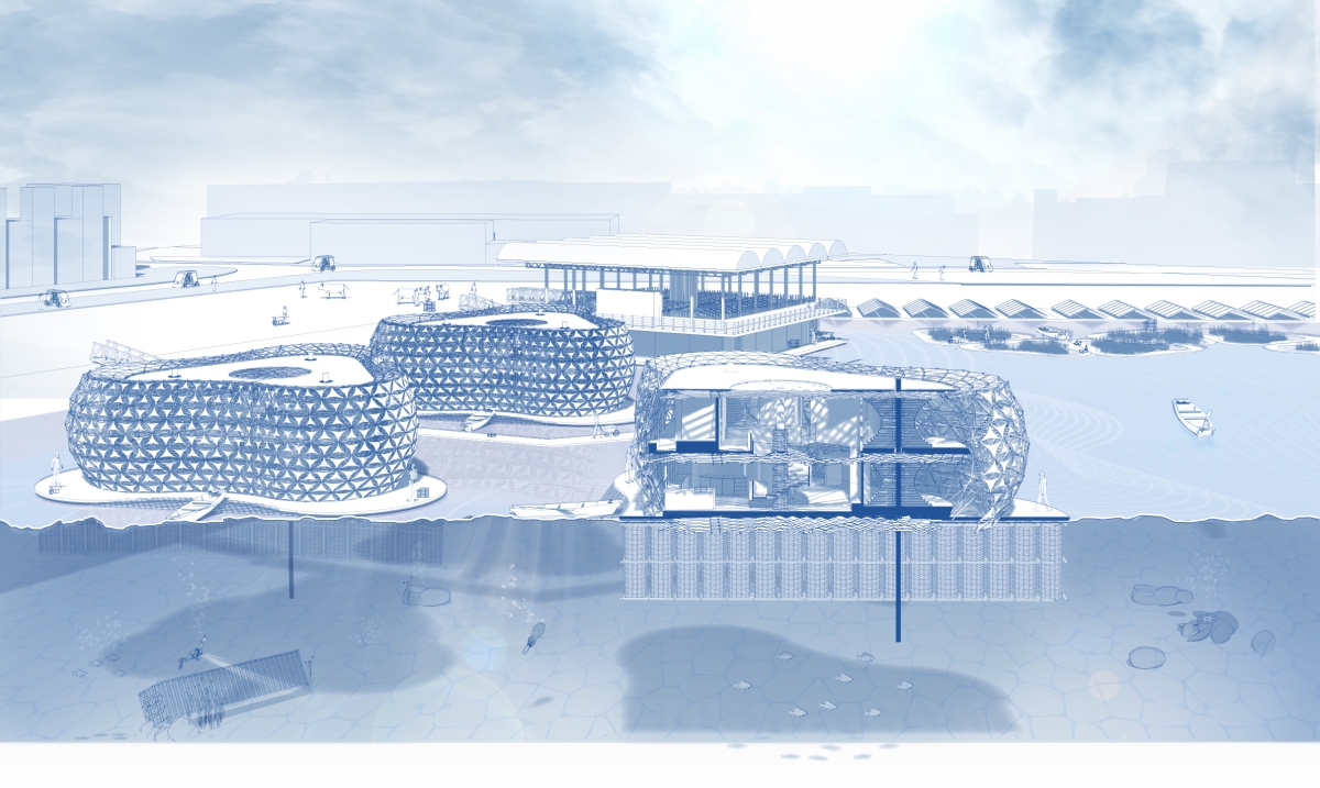
3Dimensional Greenhouse

3Dimensional Greenhouse


Regenerative urban Arcology, hosting life, work and leisure, inspired by willow rod research and testing


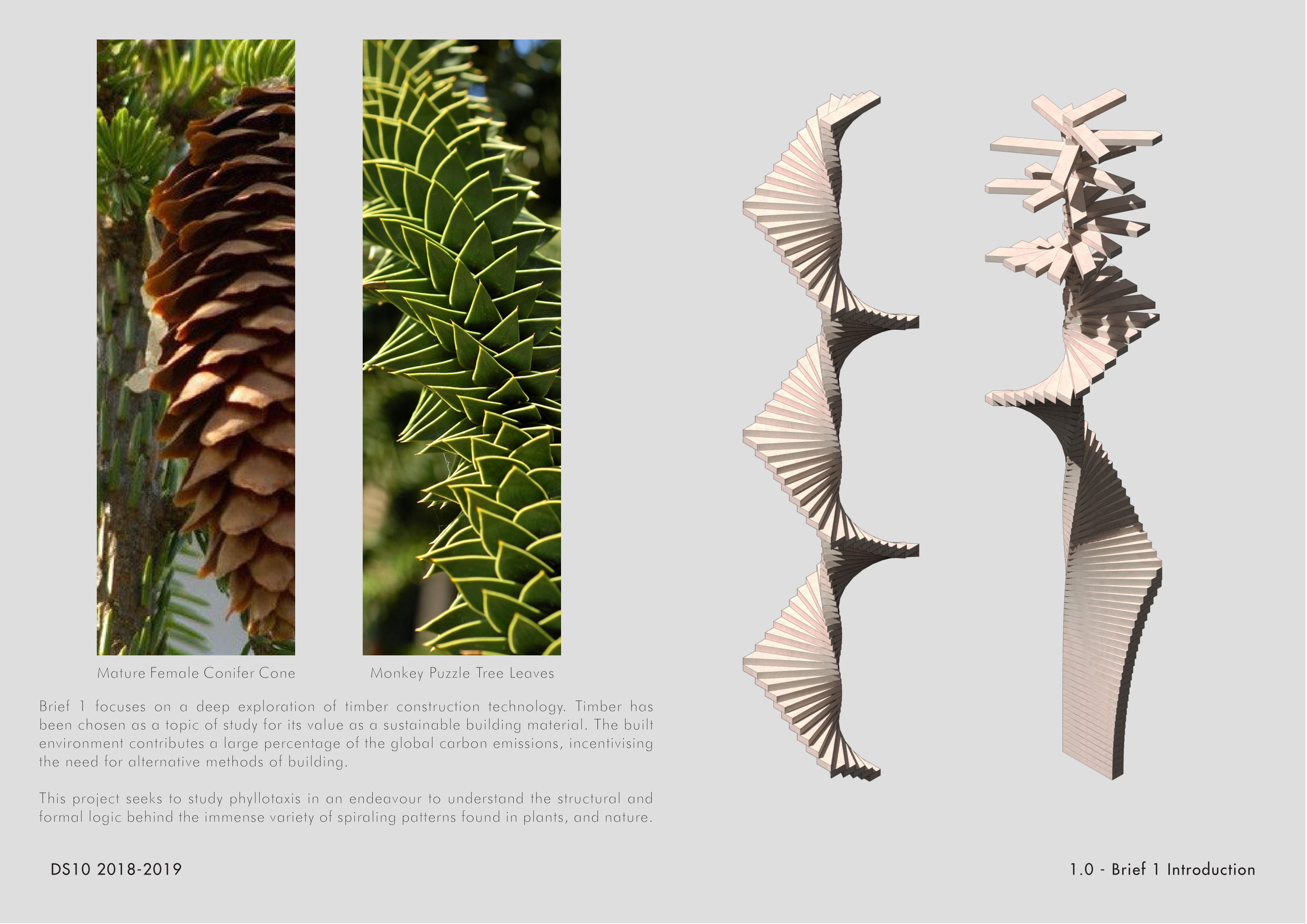
Plant rich diets & agroforestry are methods to reverse global warming from Drawdown. This project returns Plant Trade heritage to Docklands through Wardian Terrariums, self-sustaining microclimates that aid plant growth from all hemispheres. Fruit, veg & herbs are home grown within high-rise greenspaces. Inspired by the photosynthetic properties of coral, the buildings plants grow symbiotically with controlled levels of sunlight, energy, temperature & moisture.

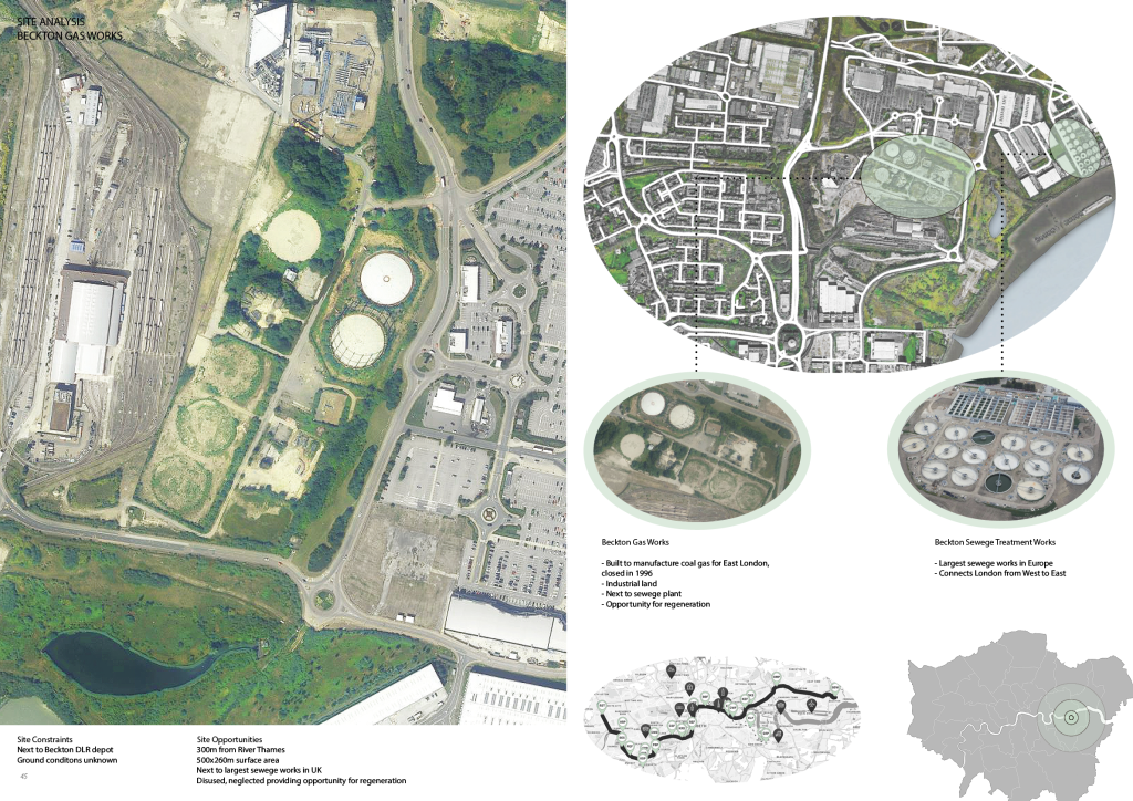
SITE: DOCKLANDS, LONDON
Rotherhithe has been selected as the site for brief 1, with Beckton as the site for brief 2. Both sites are located in Docklands.
Rotherhithe, South west London, is currently under planning with proposals to build a multi-use housing development around the gasometer. In 2019, the Rotherhithe Gas Holder company opened a temporary Hub to receive resident feedback for the planned development. Lots of feedback was in relation to the heritage of Rotherhithe, with residents requesting the history of the site is maintained and celebrated.
The name ‘Rotherhithe’ derived from the Latin translation of ‘Landing place’, as it was part of the Docklands trade, with raw materials and goods being imported to the site via ships from around the world. The proposed artefact re-creates native climates from all hemispheres for native & imported plants that grow herbs, fruits, spices and botanicals.

Rotherhithe Warehouse, 1960
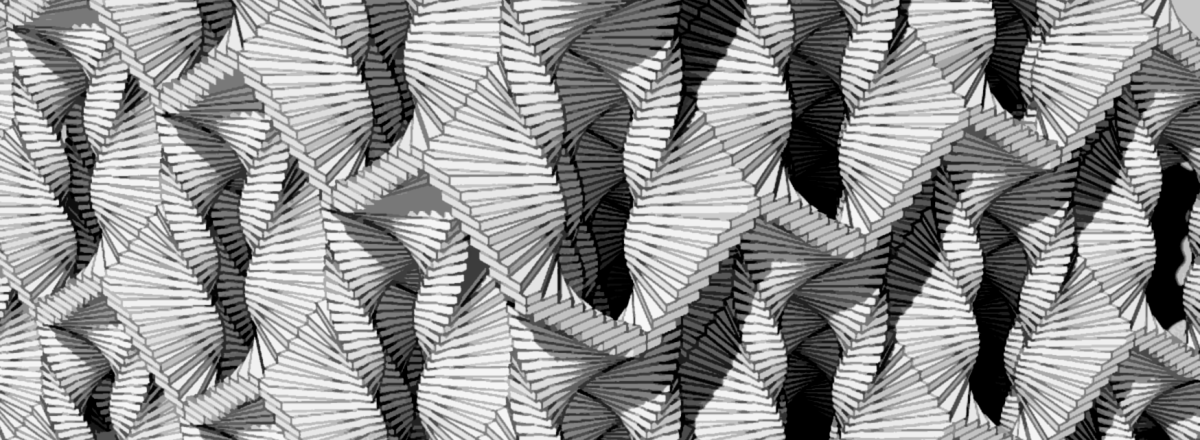
THE CLIMATE CRISIS: CORAL REGENERATION


Taking inspiration from the death of a coral skeleton after bleaching, the artefact is based on a replicated ‘mesh’ aspect of strong and resilliant branching coral.
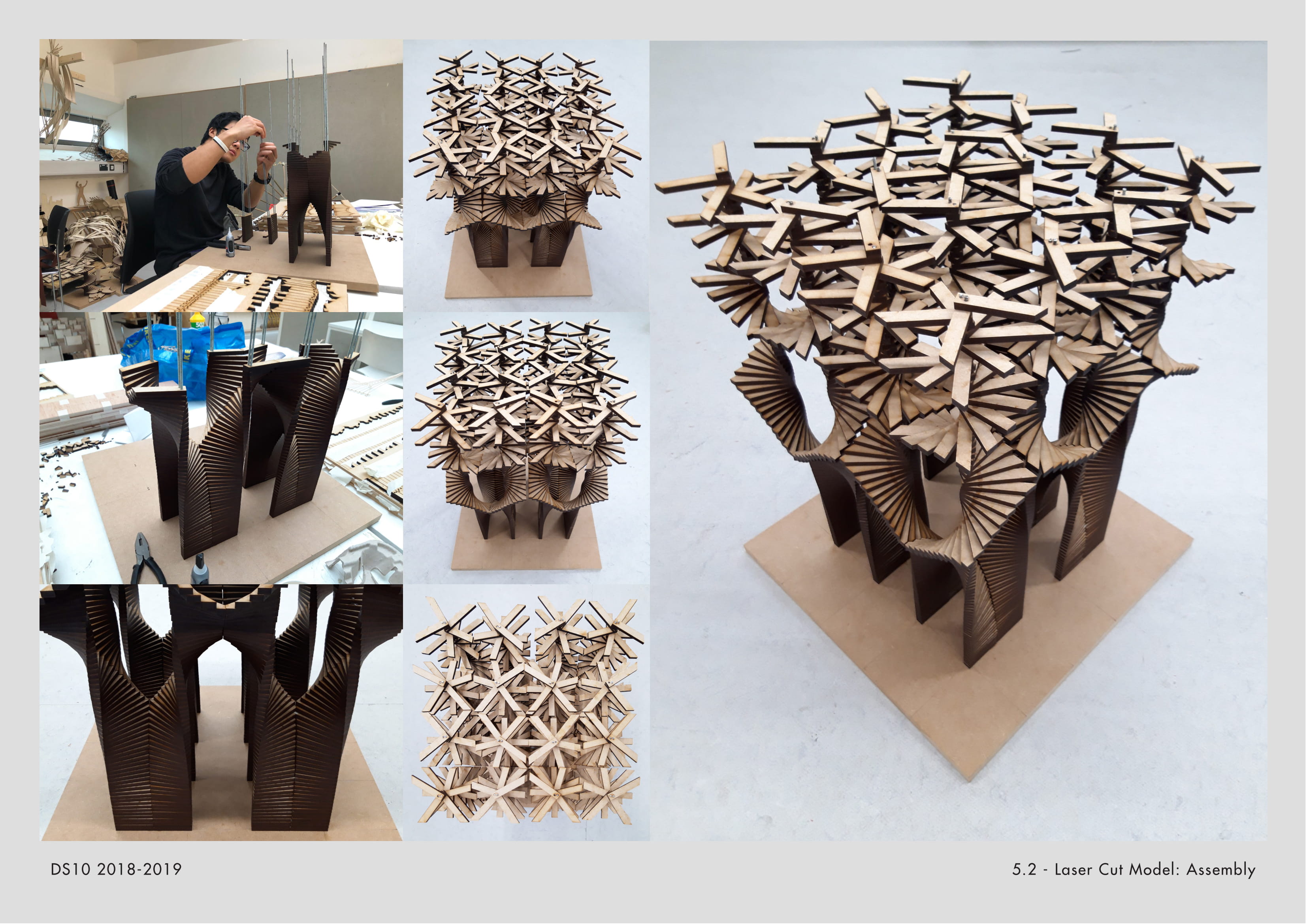
DIGITAL EXPERIMENTATION


Taking the resillience of a coral mesh, I have experimented on Grasshopper with different methods of creating the initial design concepts of my artefact. The mesh will act as a supportive shell, with plants integrated throughout.

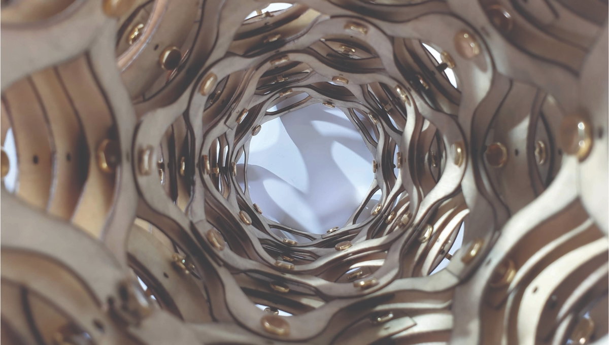
MESH TO STRUCTURE
The Grasshopper experiments are transformed into various containers based on the concept of Wardian Cases, providing various moisture, light and temperature conditions for each individual plant.
Brief 2:
HERITAGE, HORTICULTURE & HYPERBUILDS

Reviving the Docklands Plant Trade heritage through Wardian Cases
This project celebrates our scientific movements away from the industrial era through our ability to re-create self-sustaining climates for plants.
The discovery of the Wardian Case- the original terrarium, demonstrates a simple yet powerful ability to re-create its own self-sustaining climate, allowing biodiversity to grow & thrive. Docklands was the largest importer of raw materials including plants, herbs, fruits, veg & many more in the world.

‘Bio’, with the latin meaning ‘organic life’, is becoming increasingly considered through trends such as biophilia, biomimicry and biomorphism. The Biosphere (Earth), must have such trends prioritised at the forefront of design in order to help keep our planet inhabitable. Drawdown: The most comprehensive plan ever proposed to reverse global warming, is an intricately researched document on our top 100 most effective methods of reducing and reversing the climate crisis The document covers all issues concerning global warming from family planning/population control to refridgeration, plant-based diets, and organic material usage. Some of the most effective topics have been applied to my proposal are:
• Regenerative farming
• Plant rich diets
• Educating girls
• Solar energy
• Mass organic food production
The fully self-sustaining multi-functional arcological hyper building incorprates public spaces such as horticultural education, plant nurseries & labs that breed native & endangered plants, & informative public exhibitions, along with residential sectors that offer organic food farming inspired by the Wardian Case Terrariums.
Drawdown summarises ways to help reverse global warming. Regenerative farming, plant rich diets, biodiversity & permacultire are some Drawdown methods that I have incorprated into my project. Below is a full list of the methods I have included, and individual summaries of why these methods have been incorprated into my residential biodiverse tower.


The main aspects of the Corn-Crete House system are the use of space, material efficiency and relationship to site. The way space is shaped influences human behaviour. According to a research paper done by KAYVAN MADANI NEJAD in 2007 the curvilinearity of interior design directly affects the way people feel inside them. It concluded that the more curvilinear a space is the more comfortable, safe, relaxed and friendly it feels. My project builds upon this argument. Research also shows that the concrete industry is a major environment pollutant. Cement is the most damaging ingredient. I am proposing a new system which will be using less concrete & less cement thanks to: 1) corn residues partially replacing aggregate making the structure lighter and more porous 2) casting around inflatables resulting in curvilinear architecture suitable for compression which requires less tensile strength.


WHAT IS AZOLLA?

Azolla is a minuscule floating plant that forms part of a genus of species of aquatic ferns, also known as Mosquito Fern. It holds the world record in biomass producer – doubling in 2-3 days. The secret behind this plant is its symbiotic relationship with nitrogen fixing cyanobacterium Anabaena making it a superorganism. The Azolla Provides a microclimate for the cyanobacteria in exchange for nitrate fertiliser. Azolla is the only known case where a symbiotic relationship endures during the fern’s reproductive cycle and is passed on to the next generation. They also have a complimentary photosynthesis, using light from most of the visible spectrum and their growth is accelerated with elevated CO2 and Nitrogen.


Azolla is capable of producing natural biofertiliser, bioplastics because of its sugar contents and biofuel because of the large amount of lipids. Its growth requirements can accommodate many climates too, allowing it to be classified as a weed in many countries. I was able to study the necessary m2 of growing Azolla to sequester the same amount as my yearly CO2 emissions, resulting in 57% of a football field equivalent of growing Azolla to make me carbon neutral.

Why is this useful? Climate change will inevitably bring more adverse climate conditions that will put many world wide crops at risk and, as a consequence, will affect our lives. A crop that produces biomass at the speed of Azolla provides at advantage in flexibility: a soya bean can take months to grow until ready to be harvested, Azolla can be harvested twice a week. This plant has the potential to be used in the larger agricultural sector and diminish the Greenhouse Gas Emissions of one of the most pollutant sectors.

.
REAL LIFE ACTION
I contacted the Azolla Research Group at the University of Utrecht and they kindly accepted to give us a tour of their research facilities, providing us with an in-depth insight into the aquatic fern. I also decided to approach the Floating Farm with a proposal of using Azolla in their dairy process. They agreed to explore this and I put them in contact with the research team in the University of Utrecht, who are now cooperating with the dairy farm’s team in decreasing the carbon emissions of the cows on the farm.

.
ARCHITECTURAL PROPOSAL

The Floating Azolla District consists on a proposed community that emphasises a circular economy with a focus on sustainable agriculture in Rotterdam. It builds on to the existing Floating Farm found in the M4H area. It is formed of three areas:
1) Azolla – Dwellings combining a series of residential units for the increasing number of young entrepreneurs in the RID with three central cores growing stacked trays of Azolla as in vertical farming.
2) The Floating Farm which continues to produce dairy products and a Bamboo growing area to maintain the upkeep of floating platforms and construction of new dwellings. Floating rice paddies are grown in the warmer months in a closely monitored system of permaculture.
3) A production facility which concentrates on research and development into Azolla as well as retrieving the water fern’s byproducts such as bioplastics extracted from the sugars; biofuel, from the lipids; and bamboo plywood lumber for the construction of the expanding Floating District.


Floating Azolla District – Dwellings

This section concentrates on the detail construction of the Azolla-Dwellings. These floating units are designed to be used as a combination of co-housing for entrepreneurs working in the Rotterdam Innovation District, where the Floating Farm is located, and indoor Azolla growing facilities which is then used further along in the masterplan. The growing areas are built on a series of building components that provide support for trays of Azolla to be grown in a vertical farming manner and provide support for the floor plates as well as anchoring for the entire dwelling.

The materials are a combination of local bamboo grown on a series of floating platforms that prevent the cold winter winds from affecting the overall masterplan and pallets sourced from neighbouring industrial facilities. Using the reciprocal building system developed in Brief 1, a series of stacked components are linked to form the vertical farming support for the Azolla. This system is then extended to support the floors for the dwellings.
Similar to an aperture ring on a camera, this mechanism uses the varying tide to automatically collect the Azolla from the vertical farming trays to then be used throughout the Masterplan. By displacing 2.5% of the area for each tray every tidal change, this mechanism collects 50% of the harvest every 10 days allowing for a continuous growth of Azolla.


The dwellings’ facade is a result of a careful analysis of harmful and beneficial solar radiation. By setting an initial average temperature to monitory, the facade will block sun that naturally would drive the temperature above the chosen one and the beneficial would bring the temperature up. This shading serves a buffer zone that surrounds the internal living spaces and is used to grow vegetables for the residents.

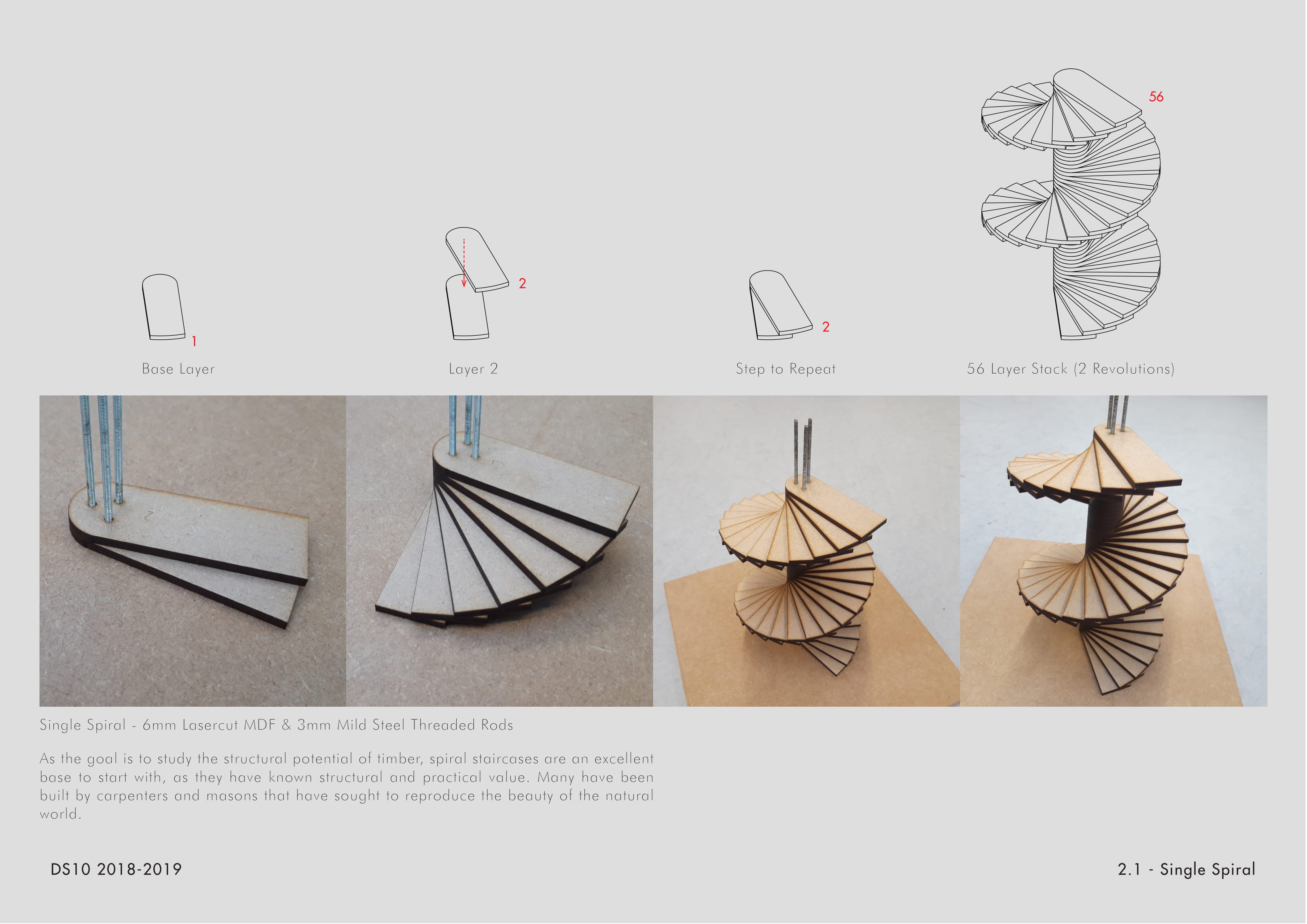
Semi-public spaces are located on the ground floor (open plan kitchen and living) and bedrooms are located on the first floor, surround a central spiral staircase for circulation.


The same building system based on reciprocal structures is coated in azolla bioplastic preventing the wood from rotting and making the form waterproof. These are used as underwater columns which allow the dwellings and platforms to float. Each ‘column’ can support a load of 2011Kg.

SITE LOCATION

Based on relationship between the University of Utrecht and the Floating Farm taking place outside the initially academic intention of the visit, I decided to use the Floating Farm as a site and a starting point for my proposal. The floating farm is intended to stand out and create an awareness of the possibility or idea of living on water and taking ownership of one’s food production, which seems to match the potential uses and benefits of Azolla. The researchers at the University of Utrecht expressed their need of getting the advantages of this plant to a wider public and this remained in my mind, possibly being the main reason behind my approach to the Floating Farm.


The Floating Farm sits in the Merwehaven area or M4H in the Port of Rotterdam. Highlighted below are the natural site conditions that determined the placement of the masterplan parts according to their function. Bamboo growing pods are placed southwards of the port to block the winter wind while allowing the summer winds from the west to navigate through.

In 2007, Rotterdam announced its ambition to become 100% climate-proof by 2025 despite having 80% of its land underwater, therefore it was important to look at the flood risk and tidal change. The Merwehaven area in Rotterdam seems to have an average tidal change of 2 metres which I thought could be taken advantage of in a mechanical system mentioned previously.


.
BUILDING SYSTEM & MATERIAL RESEARCH
The reciprocal building system used in the construction of the dwellings began by looking into the Fern plant and its’ form. All ferns are Pinnate – central axis and smaller side branches – considered a primitive condition. The veins never coalesce and are known to be ‘free’. The leaves that are broadly ovate or triangular tend to be born at right angles to the sunlight.

I then decided to model a leaf digitally, attempting to simulate the fractal nature found in a fern frond and the leaves to 3 degrees of fractals. I then simplified the fern frond to 2 levels to allow for easier laser cutting and structural stability. The large perimeter meant, therefore, there was a large amount of surface area for friction so I explored different configurations and tested their intersections.

I then selected the fern frond intersection I found to show the best stability out of the tested ones shown previously. By arraying them further, they began to curve. When pressure is applied to the top of the arch, the intersections are strengthened and the piece appears to gain structural integrity.

When a full revolution is completed, the components appear to gain their maximum structural integrity. Since I had decided to digitally model the fern frond, I was able to decrease the distance between the individual leaves in the centre of each frond through grasshopper. By doing this, the intersections connecting a frond with another were less tight in the centre than on the extremities of each frond, allowing for double curvature.

I continued to iterate the leave by decreasing any arching on the leaf and finding the minimum component, the smallest possible component in the system. By arraying a component formed of 3 ‘leaves’ on one hand and 2 on the other, I would be able to grow the system in one direction as before due to the reciprocal organisation and in the other direction by staggering the adjacent component. The stress tests of this arrangement showed a phased failure of the ‘column’. Instead of breaking at once, row by row of components failed with time, outwards-inwards.


I extracted the minimum possible component from the previous iterations and attempted to merge the system with firstly, 3d printed PLA bioplastic components and then with an algae bioplastic produced at home. I became interested in the idea of being able to coat the wood in an algae bioplastic substituting the need for any epoxy for waterproofing. The stress tests for this component showed a surprising total of 956 kg-force for it to fail.

Here, I began combining different quantities of vegetable glycerine, agar agar (extracted from red algae and used for cooking) and water. By changing the ratios of agar and glycerine I was able to create 2 different bioplastics: one being brittle and the other flexible. See above for the flexible sample and below for the brittle sample. Both samples appeared to fail under the same 7 Kg-force.
For additional information please visit:
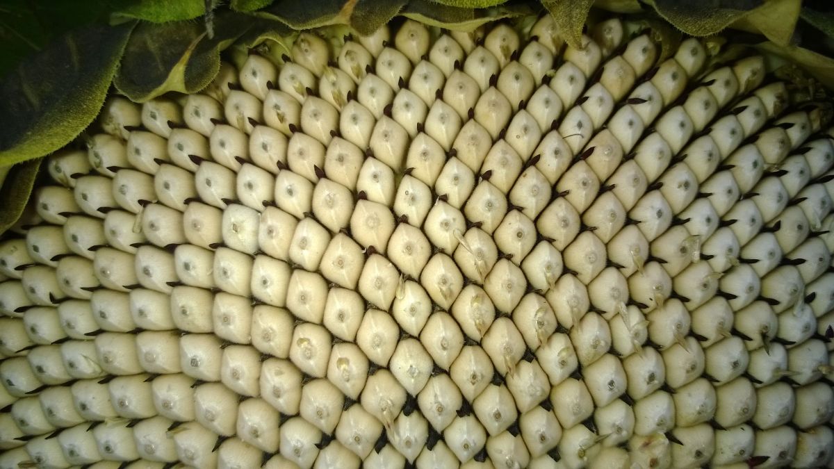
Palm trees are angiosperms, which means flowering plants. They are monocots which means their seeds produce a single, leaf-like cotyledon when they sprout. This makes palms closely related to grasses and bamboo.


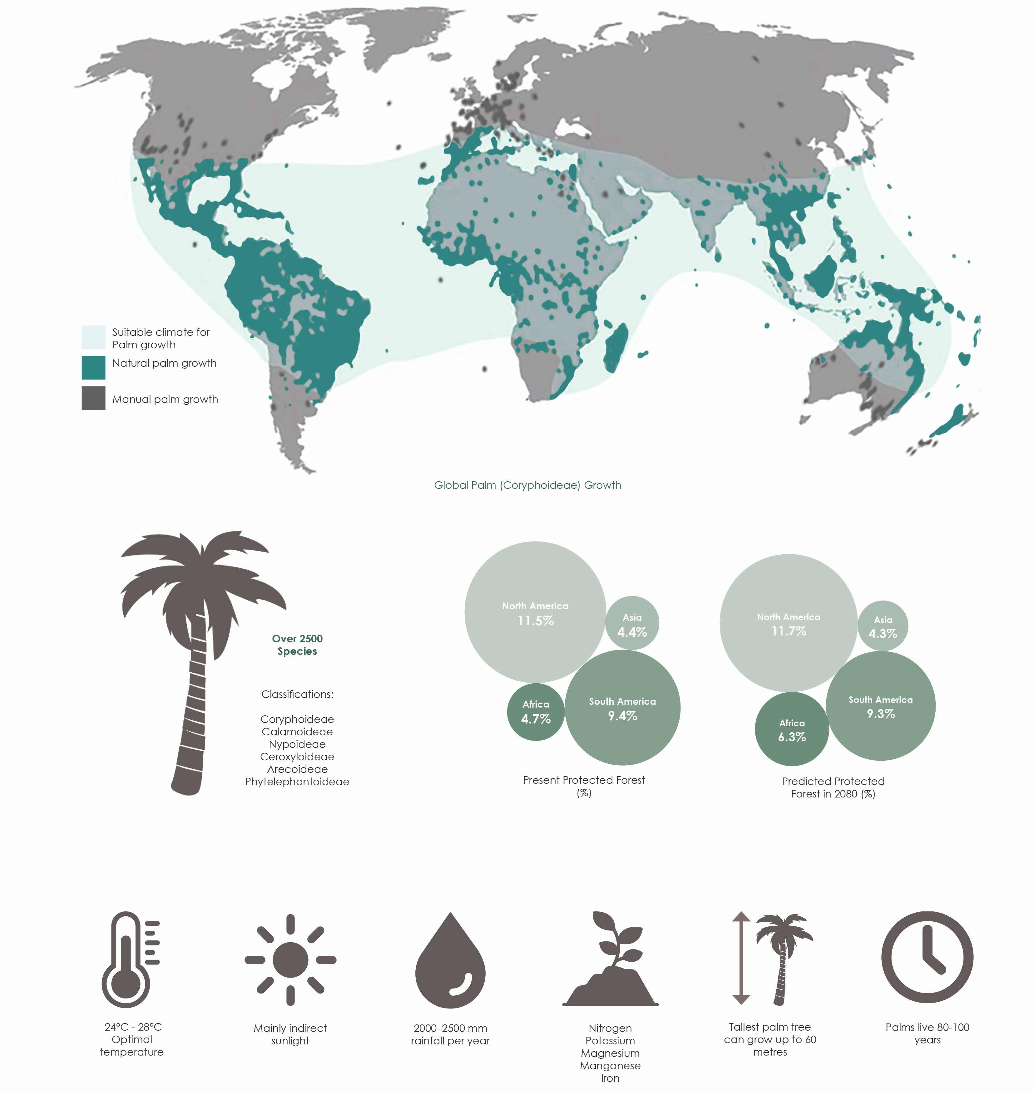
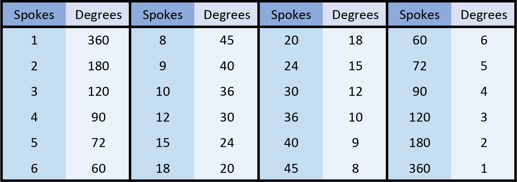
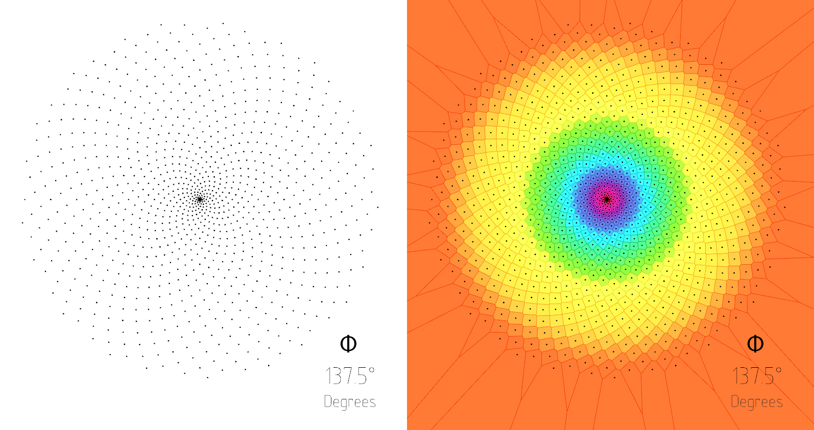
This mature palm shows how the pattern originally seen in the young plant, forms a distinct mathematic pattern known as ‘Phyllotaxis’. This is a pattern with reoccurs throughout nature and is based on the Fibonacci sequence. In order to try to understand the use and formation of the palm fibre, the overall formation of the palm stem needed to be mathematically explored.
However, redrawing the cross-section of the base of the palm plants allows a better understanding of the arrangement of the palm plant.

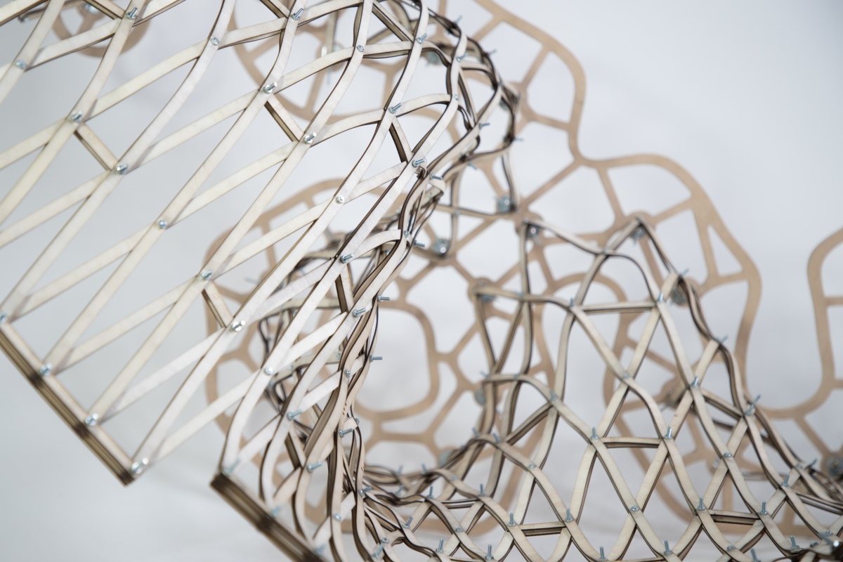
This exercise allows models to be made to recreate the patterns found in palm plants. By engineering plywood components, the basic shape of the palm geometry can be made into a physical model.

This was pushed further by curving the plywood components to make extruded palm structure models


The arrayed components can then be altered so that the base of the models form regular polygon shapes. Doing this allows the potential for the structures to be tesselated. Using different numbers of components mean the structure can then be tested for strength.

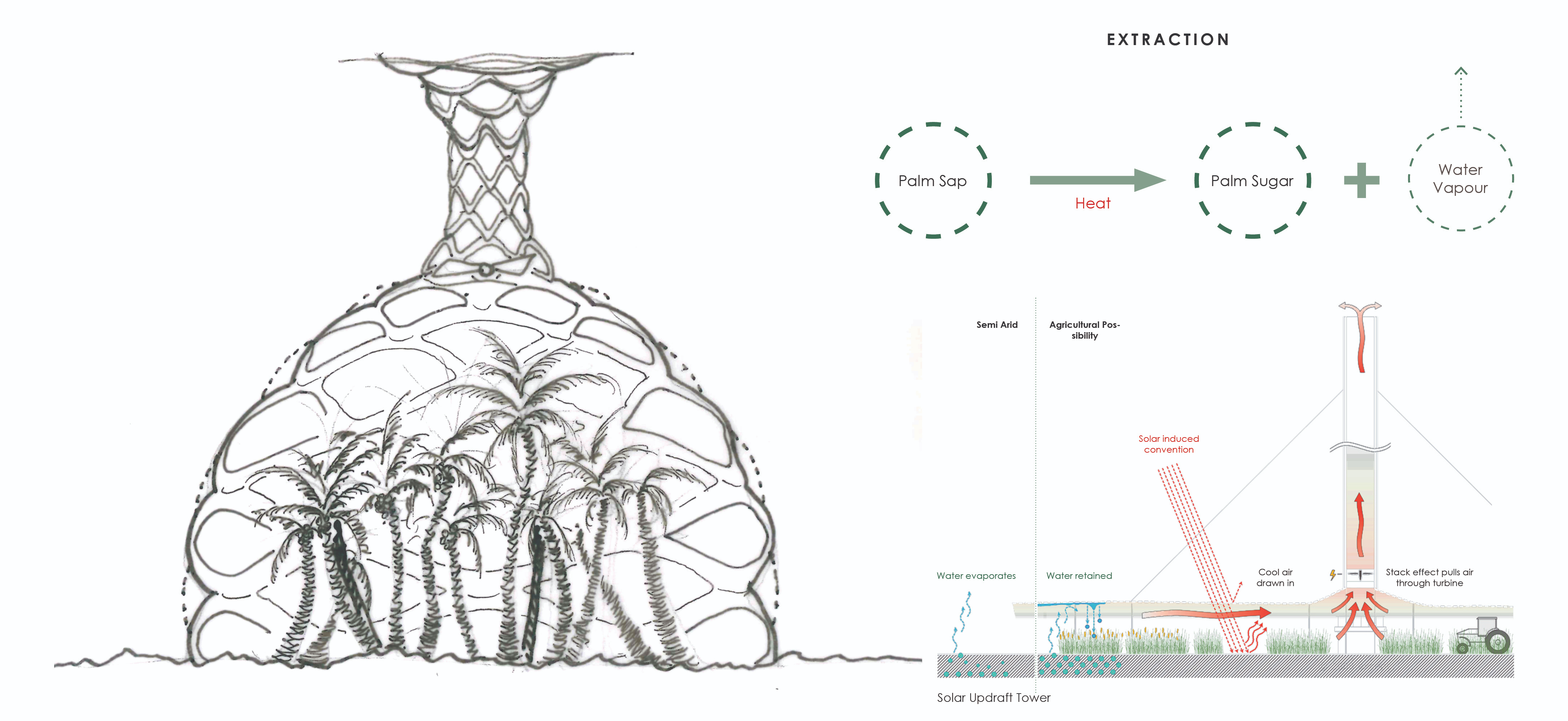
There are hundreds of used for palm fruits, this the plant producing materials which range from durable, to flexible to edible. One of the more interesting ones if the production of palm wine using the sap from the tree. Within 2 hours of the wine tapping process, the wine may reach up to 4%, by the following day the palm wine will become over fermented. Some prefer to drink the beverage at this point due to the higher alcohol content. The wine immediately begins fermenting, both from natural yeast in the air and from the remnants of wine left in the containers to add flavour. Ogogoro described a ‘local gin’, is a much stronger spirit made from Raffia palm tree sap. After extraction, the sap is boiled to form steam, which is then condensed and collected for consumption. Ogogoro is not synthetic ethanol but it is tapped from a natural source and then distilled.
To understand the fermentation process more clear, the process of fermenting sugar to make wine has been undertaken.

The distillation of the wine can be used to make bio-ethanol. This production of this fuel can act as a sustainable alternative to fossil fuel energy, which is overused and damaging to our environment.

The developed structure, as well as the production of palm wine and bio-ethanol, can be collaborated to develop a programme, which provides sustainable energy, within a space that is inviting and exciting.
The production of bio-fuel releases a lot of carbon dioxide. In order to ensure the process does not impact the environment, this needs to occur inside a closed system, so the CO2 does not enter the atmosphere. This can be done by using the properties of a Solar Updraft Tower. Carbon dioxide released from the fermentation and distillation processes can be received by palm trees for increased photosynthesis, while the excess oxygen from the trees provides fresh air for visitors.
The fermentation process can be controlled within an isolated area of the model.

The Distillation process, which requires a store of water for cooling, can also be conducted in an isolated area of the model, with apparatus incorporated into the structure.

The final proposal will be a combination of all three forms

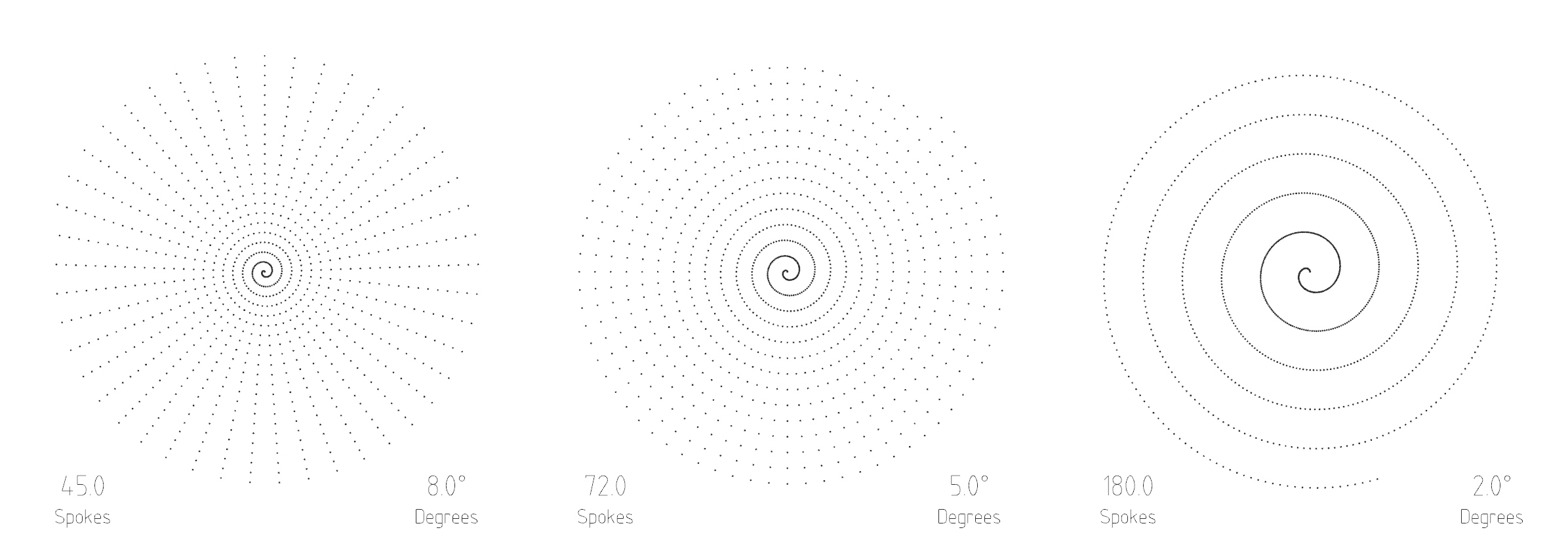
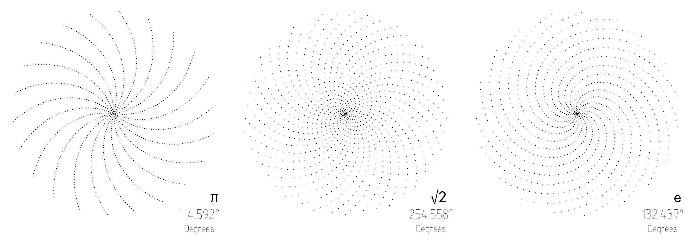
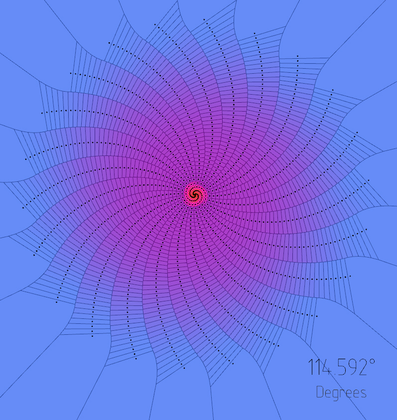
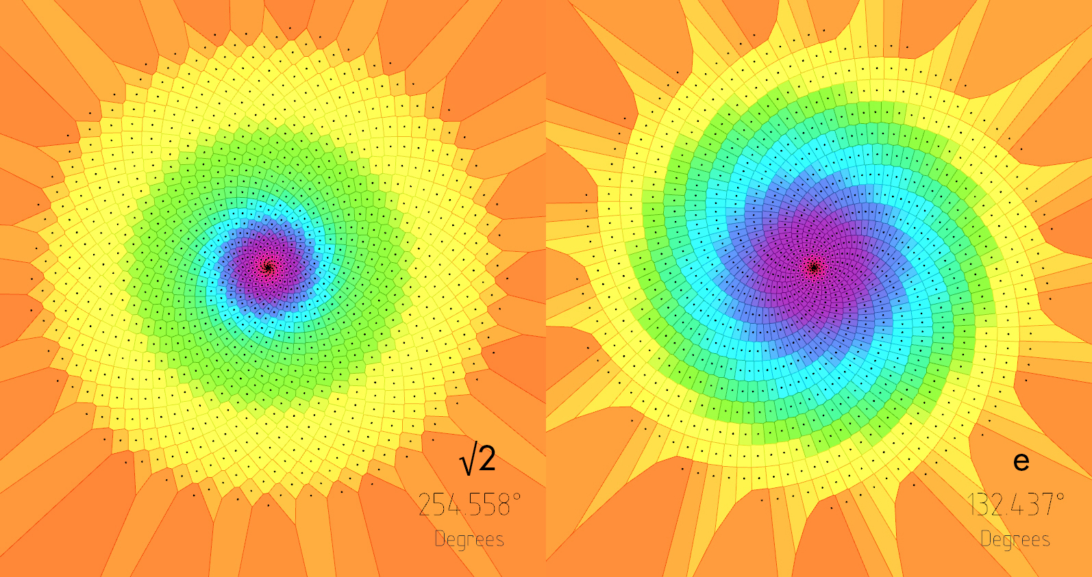
The natural world is brimming with ratios, and spirals, that have been captivating mathematicians for centuries.
Source:
Infinite fractions and the most irrational number: [Link]
The Golden Ratio (why it is so irrational): [Link]

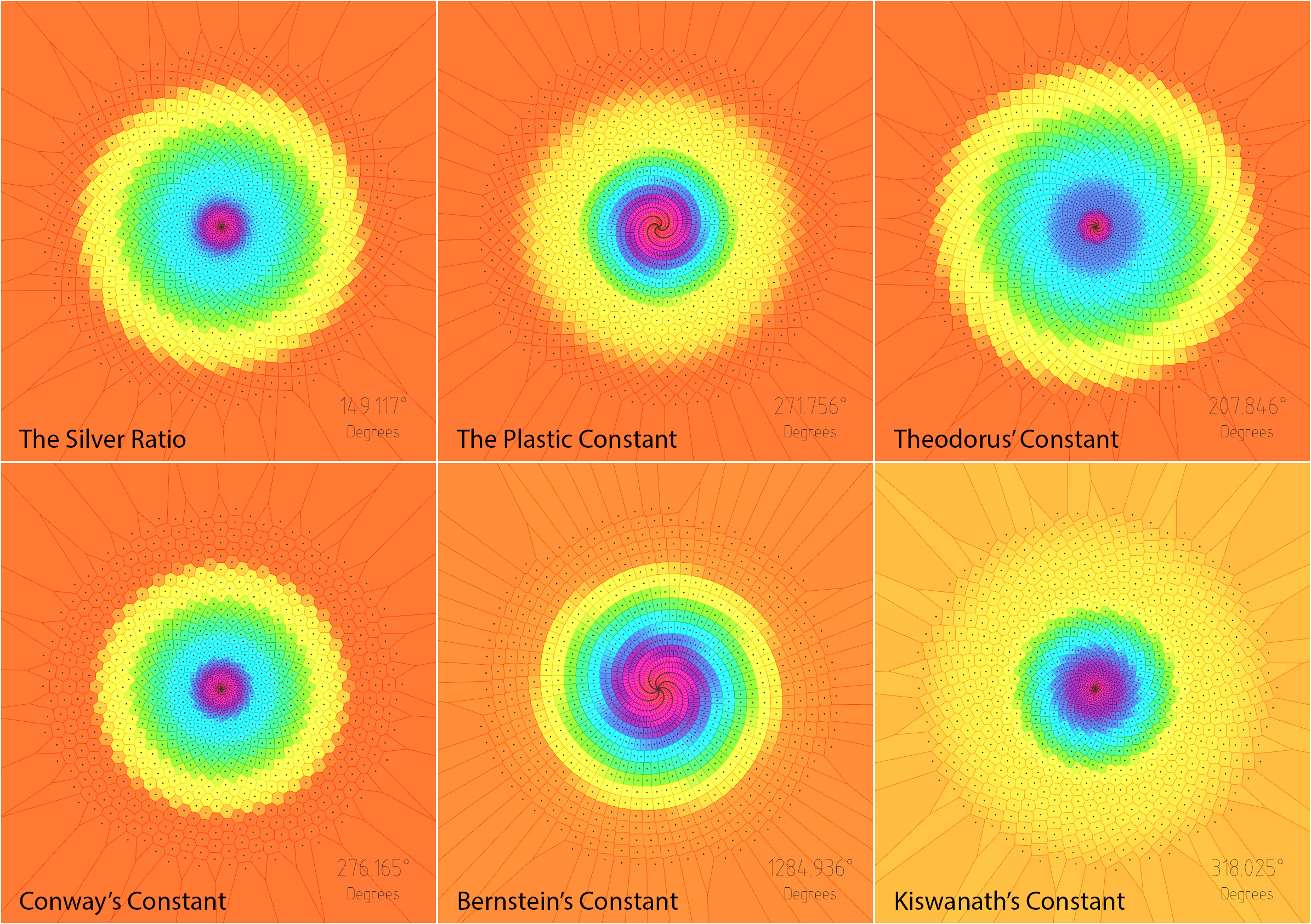
Source:
The Silver Ratio & Metallic Means: [Link]
M.C. Escher said that we adore chaos because we love to produce order. Alain Badiou also said that mathematics is a rigorous aesthetic; it tells us nothing of real being, but forges a fiction of intelligible consistency.
Grids, shells, and how they, in conjunction with the study of the natural world, can help us develop increasingly complex structural geometry.
This post is the third installment of sort of trilogy, after Shapes, Fractals, Time & the Dimensions they Belong to, and Developing Space-Filling Fractals. While it’s not important to have read either of those posts to follow this one, I do think it adds a certain level of depth and continuity.
Regarding my previous entries, it can be difficult to see how any of this has to do with architecture. In fact I know a few people who think studying fractals is pointless.
Admittedly I often struggle to explain to people what fractals are, let alone how they can influence the way buildings look. However, I believe that this post really sheds light on how these kinds of studies may directly influence and enhance our understanding (and perhaps even the future) of our built environment.
On a separate note, I heard that a member of the architectural academia said “forget biomimicry, it doesn’t work.”
Firstly, I’m pretty sure Frei Otto would be rolling over in his grave.
Secondly, if someone thinks that biomimicry is useless, it’s because they don’t really understand what biomimicry is. And I think the same can be said regarding the study of fractals. They are closely related fields of study, and I wholeheartedly believe they are fertile grounds for architectural marvels to come.
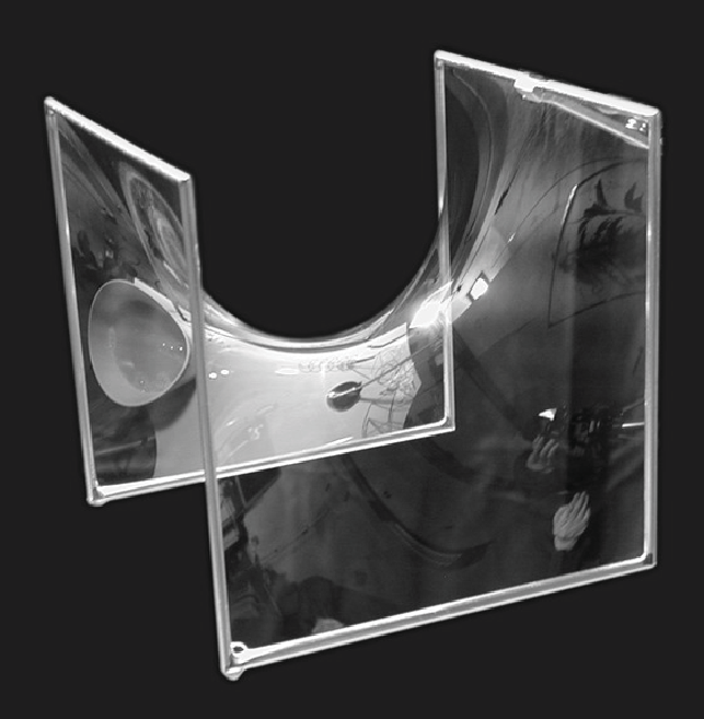
As far as classification goes, shells generally fall under the category of two-dimensional shapes. They are defined by a curved surface, where the material is thin in the direction perpendicular to the surface. However, assigning a dimension to certain shells can be tricky, since it kinda depends on how zoomed in you are.
A strainer is a good example of this – a two-dimensional gridshell. But if you zoom in, it is comprised of a series of woven, one-dimensional wires. And if you zoom in even further, you see that each wire is of course comprised of a certain volume of metal.
This is a property shared with many fractals, where their dimension can appear different depending on the level of magnification. And while there’s an infinite variety of possible shells, they are (for the most part) categorizable.
Analytic geometry is created in relation to Cartesian planes, using mathematical equations and a coordinate systems. Synthetic geometry is essentially free-form geometry (that isn’t defined by coordinates or equations), with the use of a variety of curves called splines. The following shapes were created via Synthetic geometry, where we’re calling our splines ‘u’ and ‘v.’
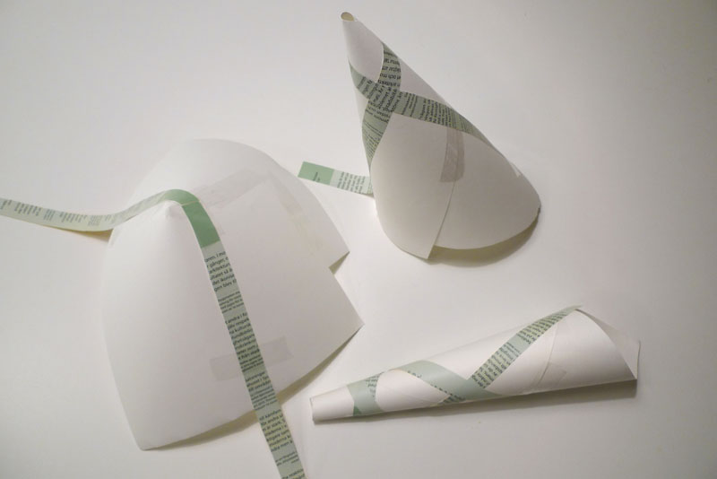
These curves highlight each dimension of the two-dimensional surface. In this case only one of the two ‘curves’ is actually curved, making this shape developable. This means that if, for example, it was made of paper, you could flatten it completely.
In this case, one of them grows in length, but the other still remains straight. Since one of the dimensions remains straight, it’s still a single curved surface – capable of being flattened without changing the area. Singly curved surfaced may also be referred to as uniclastic or monoclastic.
These can be classified as synclastic or anticlastic, and are non-developable surfaces. If made of paper, you could not flatten them without tearing, folding or crumpling them.
In this case, both curves happen to be identical, but what’s important is that both dimensions are curving in the same direction. In this orientation, the dome is also under compression everywhere.
The surface of the earth is double curved, synclastic – non-developable. “The surface of a sphere cannot be represented on a plane without distortion,” a topic explored by Michael Stevens: https://www.youtube.com/watch?v=2lR7s1Y6Zig
This shape was achieved by sweeping a straight line over a straight path at one end, and another straight path at the other. This will work as long as both rails are not parallel. Although I find this shape perplexing; it’s double curvature that you can create with straight lines, yet non-developable, and I can’t explain it..
The hyperboloid has been a popular design choice for (especially nuclear cooling) towers. It has excellent tensile and compressive properties, and can be built with straight members. This makes it relatively cheap and easy to fabricate relative to it’s size and performance.
These are singly curved curves, although that does sound confusing. A simple way to understand what geodesic curves are, is to give them a width. As previously explored, we know that curves can inhabit, and fill, two-dimensional space. However, you can’t really observe the twists and turns of a shape that has no thickness.
A ribbon is essentially a straight line with thickness, and when used to follow the curvature of a surface (as seen above), the result is a plank line. The term ‘plank line’ can be defined as a line with an given width (like a plank of wood) that passes over a surface and does not curve in the tangential plane, and whose width is always tangential to the surface.
Since one-dimensional curves do have an orientation in digital modeling, geodesic curves can be described as the one-dimensional counterpart to plank lines, and can benefit from the same definition.
The University of Southern California published a paper exploring the topic further: http://papers.cumincad.org/data/works/att/f197.content.pdf
For simplicity, here’s a basic grid set up on a flat plane:
We start by defining two points anywhere along the edge of the surface. Then we find the geodesic curve that joins the pair. Of course it’s trivial in this case, since we’re dealing with a flat surface, but bear with me.
We can keep adding pairs of points along the edge. In this case they’re kept evenly spaced and uncrossing for the sake of a cleaner grid.
After that, it’s simply a matter of playing with density, as well as adding an additional set of antagonistic curves. For practicality, each set share the same set of base points.
He’s an example of a grid where each set has their own set of anchors. While this does show the flexibility of a grid, I think it’s far more advantageous for them to share the same base points.
The same principle is then applied to a series of surfaces with varied types of curvature.
First comes the shell (a barrel vault in this case), then comes the grid. The symmetrical nature of this surface translates to a pretty regular (and also symmetrical) gridshell. The use of geodesic curves means that these gridshells can be fabricated using completely straight material, that only necessitate single curvature.
The same grid used on a conical surface starts to reveal gradual shifts in the geometry’s spacing. The curves always search for the path of least resistance in terms of bending.
This case illustrates the nature of geodesic curves quite well. The dome was free-formed with a relatively high degree of curvature. A small change in the location of each anchor point translates to a large change in curvature between them. Each curve looks for the shortest path between each pair (without leaving the surface), but only has access to single curvature.
Structurally speaking, things get much more interesting with anticlastic curvature. As previously stated, each member will behave differently based on their relative curvature and orientation in relation to the surface. Depending on their location on a gridshell, plank lines can act partly in compression and partly in tension.
While geodesic curves make it far more practical to fabricate shells, they are not a strict requirement. Using non-geodesic curves just means more time, money, and effort must go into the fabrication of each component. Furthermore, there’s no reason why you can’t use alternate grid patterns. In fact, you could use any pattern under the sun – any motif your heart desires (even tessellated puppies.)
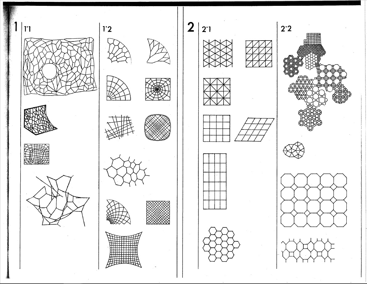
Here are just a few of the endless possible pattern. They all have their advantages and disadvantages in terms of fabrication, as well as structural potential.
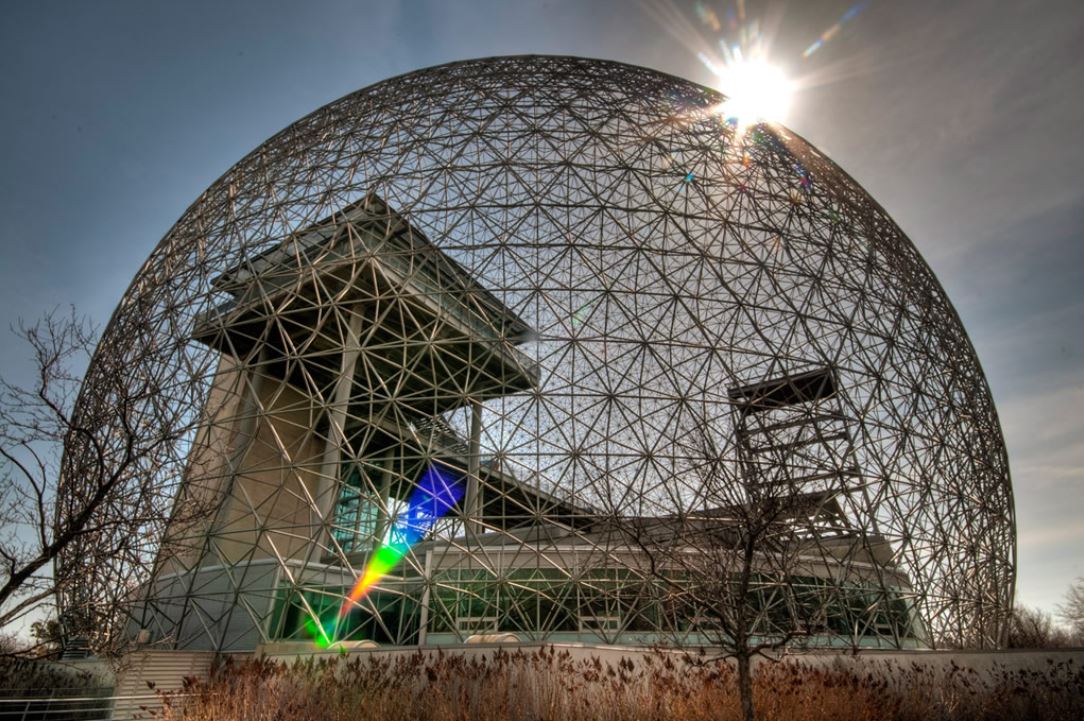
Gridshells with large amounts of triangulation, such as Buckminster Fuller’s geodesic spheres, typically perform incredibly well structurally. These structure are also highly efficient to manufacture, as their geometry is extremely repetitive.
Gridshells with highly irregular geometry are far more challenging to fabricate. In this case, each and every piece had to be custom made to shape; I imagine it must have costed a lot of money, and been a logistical nightmare. Although it is an exceptionally stunning piece of architecture (and a magnificent feat of engineering.)
In our case, building these shells is simply a matter of converting the geodesic curves into planks lines.
The whole point of using them in the first place is so that we can make them out of straight material that don’t necessitate double curvature. This example is rotating so the shape is easier to understand. It’s grid is also rotating to demonstrate the ease at which you can play with the geometry.
This is what you get by taking those plank lines and laying them flat. In this case both sets are the same because the shell happens to the identicall when flipped. Being able to use straight material means far less labour and waste, which translates to faster, and or cheaper, fabrication.
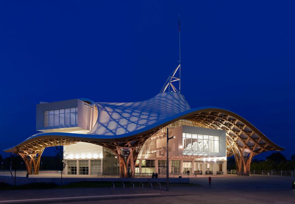
An especially crucial aspect of gridshells is the bracing. Without support in the form of tension ties, cable ties, ring beams, anchors etc., many of these shells can lay flat. This in and of itself is pretty interesting and does lends itself to unique construction challenges and opportunities. This isn’t always the case though, since sometimes it’s the geometry of the joints holding the shape together (like the geodesic spheres.) Sometimes the member are pre-bent (like Pompidou-Metz.) Although pre-bending the timber kinda strikes me as cheating thought.. As if it’s not a genuine, bona fide gridshell.
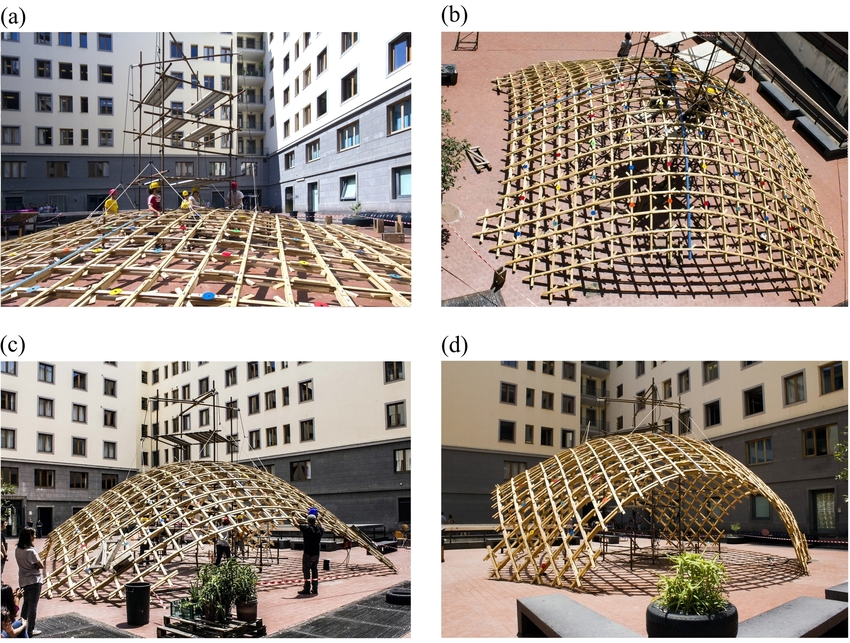
This is one of the original build method, where the gridshell is assembled flat, lifted into shape, then locked into place.
Having studied the basics makes exploring increasingly elaborate geometry more intuitive. In principal, most of the shells we’ve looked are known to perform well structurally, but there are strategies we can use to focus specifically on performance optimization.
These are surfaces that are locally area-minimizing – surfaces that have the smallest possible area for a defined boundary. They necessarily have zero mean curvature, i.e. the sum of the principal curvatures at each point is zero. Soap bubbles are a great example of this phenomenon.
Hyperbolic Paraboloid Soap Bubble [Source: Serfio Musmeci’s “Froms With No Name” and “Anti-Polyhedrons”]Soap film inherently forms shapes with the least amount of area needed to occupy space – that minimize the amount of material needed to create an enclosure. Surface tension has physical properties that naturally relax the surface’s curvature.
We can simulate surface tension by using a network of curves derived from a given shape. Applying varies material properties to the mesh results in a shape that can behaves like stretchy fabric or soap. Reducing the rest length of each of these curves (while keeping the edges anchored) makes them pull on all of their neighbours, resulting in a locally minimal surface.
Here are a few more examples of minimal surfaces you can generate using different frames (although I’d like stress that the possibilities are extremely infinite.) The first and last iterations may or may not count, depending on which of the many definitions of minimal surfaces you use, since they deal with pressure. You can read about it in much greater detail here: https://tinyurl.com/ya4jfqb2
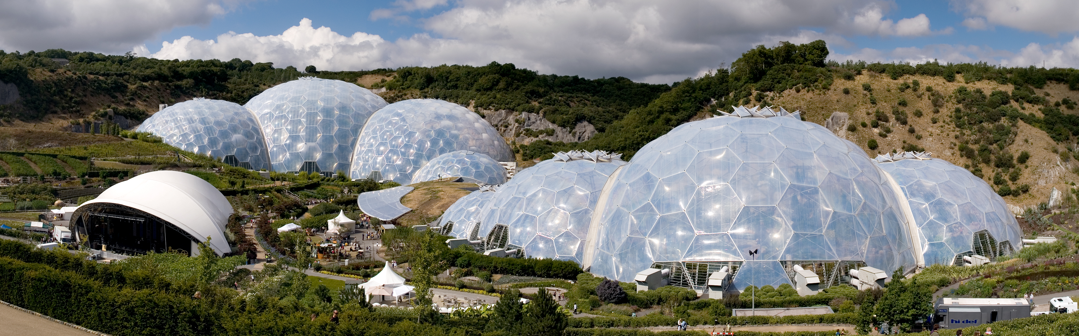
Here we have one of the most popular examples of minimal surface geometry in architecture. The shapes of these domes were derived from a series of studies using clustered soap bubbles. The result is a series of enormous shells built with an impressively small amount of material.
Triply periodic minimal surfaces are also a pretty cool thing (surfaces that have a crystalline structure – that tessellate in three dimensions):
Another powerful method of form finding has been to let gravity dictate the shapes of structures. In physics and geometry, catenary (derived from the Latin word for chain) curves are found by letting a chain, rope or cable, that has been anchored at both end, hang under its own weight. They look similar to parabolic curves, but perform differently.
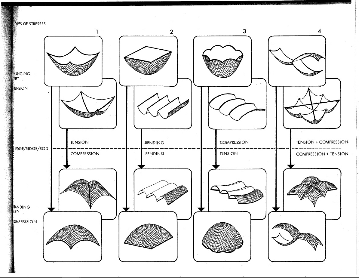
A net shown here in magenta has been anchored by the corners, then draped under simulated gravity. This creates a network of hanging curves that, when converted into a surface, and mirrored, ultimately forms a catenary shell. This geometry can be used to generate a gridshell that performs exceptionally well under compression, as long as the edges are reinforced and the corners are braced.
While I would be remiss to not mention Antoni Gaudí on the subject of catenary structure, his work doesn’t particularly fall under the category of gridshells. Instead I will proceed to gawk over some of the stunning work by Frei Otto.
Of course his work explored a great deal more than just catenary structures, but he is revered for his beautiful work on gridshells. He, along with the Institute for Lightweight Structures, have truly been pioneers on the front of theoretical structural engineering.
Frei Otto is a fine example of ecological literacy at its finest. A profound curiosity of the natural world greatly informed his understanding of structural technology. This was all nourished by countless inquisitive and playful investigations into the realm of physics and biology. He even wrote a series of books on the way that the morphology of bird skulls and spiderwebs could be applied to architecture called Biology and Building. His ‘IL‘ series also highlights a deep admiration of the natural world.
Of course he’s the not the only architect renown their fascination of the universe and its secrets; Buckminster Fuller and Antoni Gaudí were also strong proponents of biomimicry, although they probably didn’t use the term (nor is the term important.)
Gaudí’s studies of nature translated into his use of ruled geometrical forms such as hyperbolic paraboloids, hyperboloids, helicoids etc. He suggested that there is no better structure than the trunk of a tree, or a human skeleton. Forms in biology tend to be both exceedingly practical and exceptionally beautiful, and Gaudí spent much of his life discovering how to adapt the language of nature to the structural forms of architecture.
Fractals were also an undisputed recurring theme in his work. This is especially apparent in his most renown piece of work, the Sagrada Familia. The varying complexity of geometry, as well as the particular richness of detail, at different scales is a property uniquely shared with fractal nature.
Antoni Gaudí and his legacy are unquestionably one of a kind, but I don’t think this is a coincidence. I believe the reality is that it is exceptionally difficult to peruse biomimicry, and especially fractal geometry, in a meaningful way in relation to architecture. For this reason there is an abundance of superficial appropriation of organic, and mathematical, structures without a fundamental understanding of their function. At its very worst, an architect’s approach comes down to: ‘I’ll say I got the structure from an animal. Everyone will buy one because of the romance of it.”
That being said, modern day engineers and architects continue to push this envelope, granted with varying levels of success. Although I believe that there is a certain level of inevitability when it comes to how architecture is influenced by natural forms. It has been said that, the more efficient structures and systems become, the more they resemble ones found in nature.
Euclid, the father of geometry, believed that nature itself was the physical manifestation of mathematical law. While this may seems like quite a striking statement, what is significant about it is the relationship between mathematics and the natural world. I like to think that this statement speaks less about the nature of the world and more about the nature of mathematics – that math is our way of expressing how the universe operates, or at least our attempt to do so. After all, Carl Sagan famously suggested that, in the event of extra terrestrial contact, we might use various universal principles and facts of mathematics and science to communicate.