The initial aspiration of the project was to produce a method of simplifying the construction of the 5 regular platonic solids (Tetrahedron, Cube, Octahedron, Dodecahedron and Icosahedron) using only bend active timber and simple bolted connections, eliminating the need for complex nodal connections as seen in geodesic dome construction and other compound angle connections.
Bend active timber being the main research topic, the structural capabilities and bending radii of plywood were physically tested incorporating the several thicknesses and crucially the direction of the bend either being parallel or perpendicular to the grain, resulting in an informative results matrix.
Digital explorations were undertaken for each of the platonic solids creating various sized volumetric frame structures. The resultant sizes were due to each component being constrained to fit on a standard 2440x1220mm plywood sheet and the resultant bending radius
Following physical investigations of each, the cube was taken forward as it was; more efficient in terms of material usage, easier method of assembly comparatively and unintentionally produced a deployable mechanism similar to the famous Hoberman’s sphere.
The system utilizes identical components meaning the fabrication process can be quickly and easily performed using a CNC machine, with assembling being intuitive, not requiring different parts or specialised assembly instructions. The components were cut using my own CNC and were then simply assembled by hand using bolted connections to create the skeletal frame. Assembly was extremely quick, from flat components to finished volumetric module taking only 20 minutes.
The pre-fabricated modules can then be replicated and scaled, to suit various habitable typologies a community would need or can be used individually as a deployable shelter for the homeless/emergency relief.
The natural world is brimming with ratios, and spirals, that have been captivating mathematicians for centuries.
1.0 Phyllotaxis Spirals
The term phyllotaxis (from the Greek phullon ‘leaf,’ and taxis ‘arrangement) was coined around the 17th century by a naturalist called Charles Bonnet. Many notable botanists have explored the subject, such as Leonardo da Vinci, Johannes Kepler, and the Schimper brothers. In essence, it is the study of plant geometry – the various strategies plants use to grow, and spread, their fruit, leaves, petals, seeds, etc.
1.1 Rational Numbers
Let’s say that you’re a flower. As a flower, you want to give each of your seeds the greatest chance of success. This typically means giving them each as much room as possible to grow, and propagate.
Starting from a given center point, you have 360 degrees to choose from. The first seed can go anywhere and becomes your reference point for ‘0‘ degrees. To give your seeds plenty of room, the next one is placed on the opposite side, all the way at 180°. However the third seed comes back around another 180°, and is now touching the first, which is a total disaster (for the sake of the argument, plants lack sentience in this instance: they can’t make case-by-case decisions and must stick to one angle (the technical term is a ‘divergence angle‘)).
Phyllotaxis Study: 180° (see corn leaves), 90° (see mint leaves), and 72° (see gentiana petals)
Next time you only go to 90° with your second seed, since you noticed free space on either side. This is great because you can place your third seed at 180°, and still have room for another seed at 270°. Bad news bears though, as you realise that all your subsequent seeds land in the same four locations. In fact, you quickly realise that any number that divides 360° evenly yields exactly that many ‘spokes.’
Phyllotaxis Study – 1,000 Seed Spread: 45°, 36°, and 20°
Note: This is technically true with numbers as high as 120, 180, or even 360(a spoke every 1°.) However the space between seeds in a spoke gradually becomes greater than the space between spokes themselves, leaving you with one big spiral instead.
Phyllotaxis Study – 1,000 Seed Spread: 8°, 5°, and 2°
1.2 Irrational Numbers
These ‘spokes’ are the result of the periodic nature of a circle. When defining an angle for this experiment, the more ‘rational’ it is, the poorer the spread will be (a number is rational if it can be expressed as the ratio of two integers). Naturally this implies that a number can be irrational.
Sal Khan has a great series of short videos going over the difference between the two [Link]. For our purposes, the important take-aways are:
-Between any two rational numbers, there is at least on irrational number.
–Irrational numbers go on and on forever, and never repeat.
You go back to being a flower.
Since you’ve just learned that an angle defined by a rational number gives you a lousy distribution, you decide to see what happens when you use an angle defined by an irrational number. Luckily for you, some of the most famous numbers in mathematics are irrational, like π (pi), √2 (Pythagoras’ constant), and e (Euler’s number). Dividing your circle by π (360°/3.14159…) leaves you with an angle of roughly 114.592°. Doing the same with √2 and e leave you with 254.558° and 132.437° respectively.
Phyllotaxis Growth Study: Pi, Square Root of 2, and Euler’s Number
Great success. These angles are already doing a much better job of dispersing your seeds. It’s quite clear to you that √2 is doing a much better job than π, however the difference between √2 and e appears far more subtle. Perhaps expanding these sequences will accentuate the differences between them.
Phyllotaxis Study – 1,000 Seed Spread: Pi, Square Root of 2, and Euler’s Number
It’s not blatantly obvious, but √2 appears to be producing a slightly better spread. The next question you might ask yourself is then: is it possible to measure the difference between the them? How can you prove which one really is the best? What about Theodorus’, Bernstein’s, or Sierpiński’s constants? There are in fact an infinite amount of mathematical constants to choose from, most of which do not even have names.
1.3 Quantifiable irrationality
Numbers can either be rational or irrational. However some irrational numbers are actually more irrational than others. For example, π is technically irrational (it does go on and on forever), but it’s not exceptionally irrational. This is because it’s approximated quite well with fractions – it’s pretty close to 3+1⁄7 or 22⁄7. It’s also why if you look at the phyllotaxis pattern of π, you’ll find that there are 3 spirals that morph into 22 (I have no idea how or why this is. It’s pretty rad though).
Phyllotaxis Voronoi Diagram – Proximity to Closest Neighbour: Pi
Generating a voronoi diagram with your phyllotaxis patterns is a pretty neat way of indicating exactly how much real estate each of your seeds is getting. Furthermore, you can colour code each cell based on proximity to nearest seed. In this case, purple means the nearest neighbour is quite close by, and orange/red means the closet neighbour is relatively far away.
Phyllotaxis Voronoi Diagram – Proximity to Closest Neighbour: Square Root of 2, and Euler’s Number
Congratulations! You can now empirically prove that √2 is in fact more effective than e at spreading seeds (e‘s spread has more purple, blue, and cyan, as well as less yellow (meaning more seeds have less space)). But this begs the question: how then, can you find the most irrational number? Is there even such a thing?
You could just check every single angle between 0° and 360° to see what happens.
This first thing you (by which ‘you,’ I mean ‘I’) notice is: holy cats, that’s a lot of options to choose from; how the hell are you suppose to know where to start?
The second thing you notice is that the pattern is actually oscillating between spokes and spirals, which makes total sense! What you’re effectively seeing is every possible rational angle (in order), while hitting the irrational one in between. Unfortunately you’re still not closer to picking the most irrational one, and there are far too many to compare one by one.
1.4 Phi
Fortunately you don’t have to lose any sleep over this, because there is actually a number that has been mathematically proven to be the most irrational of all. This number is called phi (a.k.a. the Golden/Divine + Ratio/Mean/Proportion/Number/Section/Cut etc.), and is commonly written as Φ (uppercase), or φ (lowercase).
It is the most irrational number because it is the hardest to approximate with fractions. Any number can be represented in the form of something called a continued fraction. Rational numbers have finite continued fractions, whereas irrational numbers have ones that go on forever. You’ve already learned that π is not very irrational, as it’s value is approximated pretty well quite early on in its continued fraction (even if it does keep going forever). On the other hand, you can go far further in Φ‘s continued fraction and still be quite far from its true value.
Source: Infinite fractions and the most irrational number: [Link] The Golden Ratio (why it is so irrational): [Link]
Since you’re (by which ‘you’re,’ I mean I’m) a flower (by which ‘a flower,’ I mean ‘an architecture student’), and not a number theorist, it’s less important to you why it’s so irrational, and more so just that it is so. So then, you plot your seeds using Φ, which gives you an angle of roughly 137.5°.
Phyllotaxis Study: The Golden Ratio
It seems to you that this angle does a an excellent job of distributing seeds evenly. Seeds always seem to pop up in spaces left behind by old ones, while still leaving space for new ones.
Phyllotaxis Voronoi Diagram – Proximity to Closest Neighbour – 1,000 Seed Spread: The Golden Ratio
Expanding the this pattern, as well as the generation of a voronoi diagram, further supports your observations. You could compare Φ‘s colour coded voronoi/proximity diagram with the one produced using √2, or any other irrational number. What you’d find is that Φ does do the better job of evenly spreading seeds. However √2 (among with many other irrational numbers) is still pretty good.
1.5 The Metallic Means & Other Constants
If you were to plot a range of angles, along with their respective voronoi/proximity diagrams, you can see there are plenty of irrational numbers that are comparable to Φ (even if the range is tiny). The following video plots a range of only 1.8°, but sees six decent candidates. If the remaining 358.2° are anything like this, then there could easily well over ten thousand irrational numbers to choose from.
It’s worth noting that this is technically not how plants grow. Rather than being added to the outside, new seeds grow from the middle and push everything else outwards. This also happens to by why phyllotaxis is a radial expansion by nature. In many cases the same is true for the growth of leaves, petals, and more.
It’s often falsely claimed that the Φ shows up everywhere in nature. Yes, it can be found in lots of plants, and other facets of nature, but not as much as some people mi
ght have you believe. You’ve seen that there are countless irrational numbers that can define the growth of a plant in the form of spirals. What you might not know is that there is such as thing as the Silver Ratio, as well as the Bronze Ratio. The truth is that there’s actually a vast variety of logarithmic spirals that can be observed in nature.
Phyllotaxis Voronoi /Proximity Study: Various Known Mathematical Constants
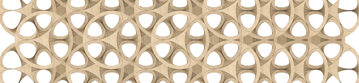
A huge variety of plants have been observed to exhibit spirals in their growth (~80% of the 250,000+ different species (some plants even grow leaves at 90° and 180° increments)). These patterns facilitate photosynthesis, give leaves maximum exposure to sunlight and rain, help moisture spiral efficiently towards roots, and or maximize exposure for insect pollination. These are just a few of the ways plants benefit from spiral geometry.
Some of these patterns may be physical phenomenons, defined by their surroundings, as well as various rules of growth. They may also be results of natural selection – of long series of genetic deviations that have stood the test of time. For most cases, the answer is likely a combination of these two things.
In some of the cases, you could make an compelling arrangement suggesting that these spirals don’t even exist. This quickly becomes a pretty deep philosophical question. If you put a series of points in a row, one by one, when does it become a line? How close do they have to be? How many do you have to have? The answer is kinda slippery, and subjective. A line is mathematically defined by an infinite sum of points, but the brain is pretty good at seeing patterns (even ones that don’t exist).
M.C. Escher said that we adore chaos because we love to produce order. Alain Badiou also said that mathematics is a rigorous aesthetic; it tells us nothing of real being, but forges a fiction of intelligible consistency.
PURSUIT is an interactive art installation that celebrates humanity’s ongoing quest for Peace, Freedom and Joy – in Life, Love and Art. The design aims to create an interactive and unique sculptural playground for visitors of the 2016 Burning Man Festival, which takes place from August 28th to September 5th in Black Rock Desert, Nevada.
THE PROJECT
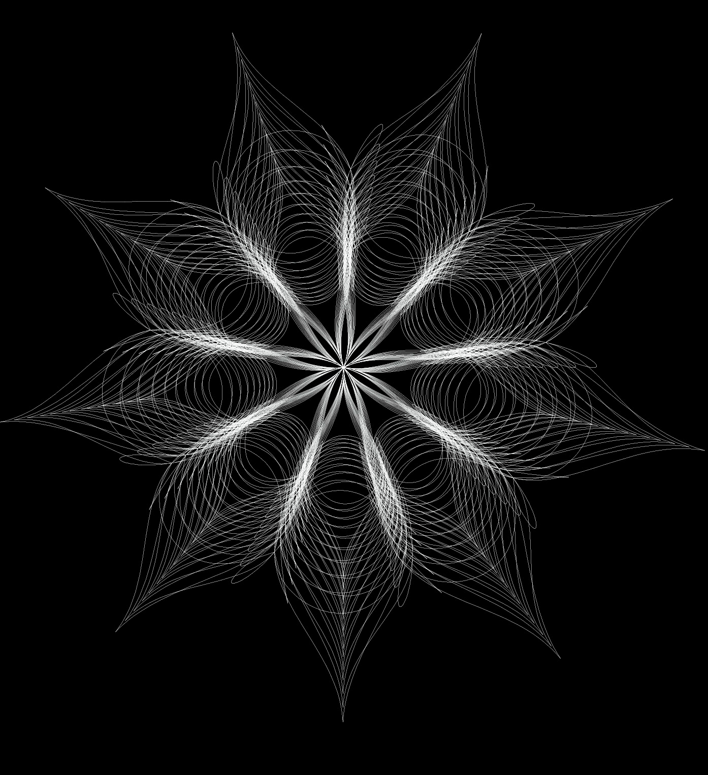
PURSUIT emerges from the playa in tiers of intertwined timber elements that ascend seamlessly in unison to form a series of congregation and celebratory spaces. The final design is the result of a year-long study into the sensuous geometry generated from a mathematical theory known as Pursuit Curvature. This theory was explored as I wanted to utilise something that could fully embody the notion of people coming together from different places and striving towards a common goal. With Pursuit Curvature, each point starts at a unique position of a polygon, and moves incrementally towards the nearest adjacent point until they all converge in the centre. The path travelled is directly influenced by the points around it, so the final curves represent the effects all of the points have on one another as a group.
Central Space
Burners can rest inside the ornate central space of Pursuit, which frames the ongoings of the playa and provides burners with a place of respite from the open sun. The six inhabitable pillars connect the playa directly to the platforms that lie atop Pursuit. Here, a glorious vantage point in which to congregate and take in the festival is gifted to Burners. During the day the interiors of the pillars are concealed from the elements, and their curved form helps to guides burners ascent to the open air. Here they can bathe in the wondrous light of either sunrise or sunset, a truly magical playa experience indeed.
At night time each pillar’s interior is powerfully lit to envelop the burners in light, so they can experience a sense of weightlessness and freedom. The soft glow emanating from each of the pillars’ cores invites burners to commune atop Pursuit to celebrate the radiant beauty of the night sky.
OUR PURSUIT
Interior of each Pillar
“As I look back on my life, I realise that every time I thought I was being rejected from something good, I was actually being re-directed to something better.” – Steve Maroboli.
Pursuit is a gift to the Burning Man community. Every year, we apply for funding from the Black Rock City LLC (Burning Man) to help fund our projects. Unfortunately this year, nobody received funding towards their project. Despite initial disappointment, I realised that this helped elevate the project’s intent and concept to a new level than originally planned. By crowdfunding the entirety of the project, we can manifest the collective Pursuit of people from all over the world to see this project built. This is not only tremendously exciting, but also a very humbling prospect, in that we have a passion to give this gift to the playa, but we need your help to give that gift. It is through this collective pursuit that we can embody the spirit of the festival and the project in a built architectural form.
REWARDS
To show our gratitude for any of your generous pledges, I have created some truly beautiful and unique rewards for all levels of contribution – Each inspired by the projects form and concept, that are all exclusive to this campaign. Please do go and have a look for yourself at them and support the campaign. If you can’t spare a donation at this time, then please share the campaign to as many people as you can – so that together, we can make the project a reality.
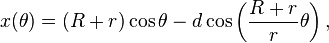
The first part of the research focused on the pattern, folds and strips of a spiral pleat origami. A strip of rectangles or trapeziums is divided by equally spaced mountain folds,then sloping parallel valley folds are placed diagonally between the mountains to connect them. The complete pattern of folds can be drawn in one continuos zigzag line. Collapsed flat, it will resemble a circular rosette. It can also be made from shapes other than a rectangular strip, such as a very long triangle or a very long rhombus.The Helicoid
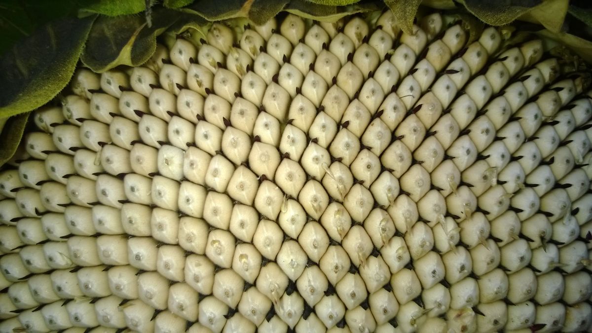
Discovered by Meusnieur in 1776. The helicoid is the only known ruled minimal surface,nother than a plane. It also has the interesting property that, while its topology is finite, its Gaussian curvature is infinite (when v = 0).
Definition
A helicoid has the following parametric equation:
x (u, v) a v Cos (u)
y (u, v) = a v Sin (u)
z (u, v) bu
Geometrically, the helicoid is defined by simultaneously rotating and translating a line at constant speed about an axis to which it is perpendicular. A parametrized helicoid. The function (u,v)=(ucosv,usinv,v) parametrizes a helicoid when (u,v) E D, where D is the rectangle [0,1]Å~[0,2]. The region D, shown as the rectangle in the first panel. The region D is divided into small rectangles which are mapped to “curvy rectangles” on the surface. You can click any of the borders of the small rectangles to highlight a curve where one of the variables is constant. Vertical lines in the rectangle D represent curves where u is constant; these correspond to curves that spiral up the helicoid. Horizontal lines in the rectangle D represent curves where v is constant; these correspond to lines that cut across the helicoid.The research into helicoid surfaces led to experiments with Curved Crease Origami. Experiments were done by cutting different shaped components out of the folded helicoid and connecting them together.Physical model
The structure is made out of six identical modules creating a volume. Each module consist of 14 arch-shaped strips that are laser cut and fixed together by attaching each strip on to a piece of fabric. This technique allows the surface to be folded in mountain and valley folds, where by introducing concentric folds to a flat surface allows the surface to bend freely and flexibly. Each module is placed in a circular pattern and laced together with string at each ends. Once attached, every second connection point is tied together towards the centre.
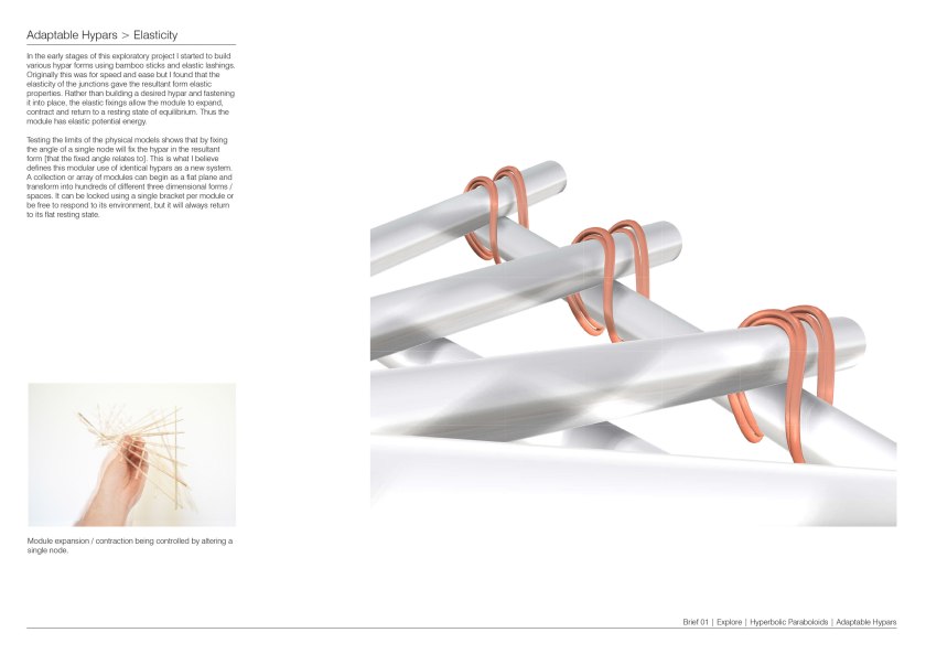
An exploration of the simplest Hyperbolic Paraboloidic ‘saddle’ form has lead to the development of a modular system that combines the principles of the hypar (Hyperbolic Paraboloid) and elastic potential energy.
A hyperbolic paraboloid is an infinite doubly ruled surface in three dimensions with hyperbolic and parabolic cross-sections. It can be parametrized using the following equations:
Mathematical: z = x2 – y2 or x = y z
Parametric: x(u,v)=u y(u,v)=v z(u,v)=uv
The physical manifestation of the above equations can be achieved by constructing a square and forcing the surface area to minimalise by introducing cross bracing that has shorter lengths than the square edges.
A particular square hypar defined by b = n * √2 (b=boundary, n=initial geometry or ‘cross bracing’) thus constricting the four points to the corners of a cube leads to interesting tessellations in three dimensions.
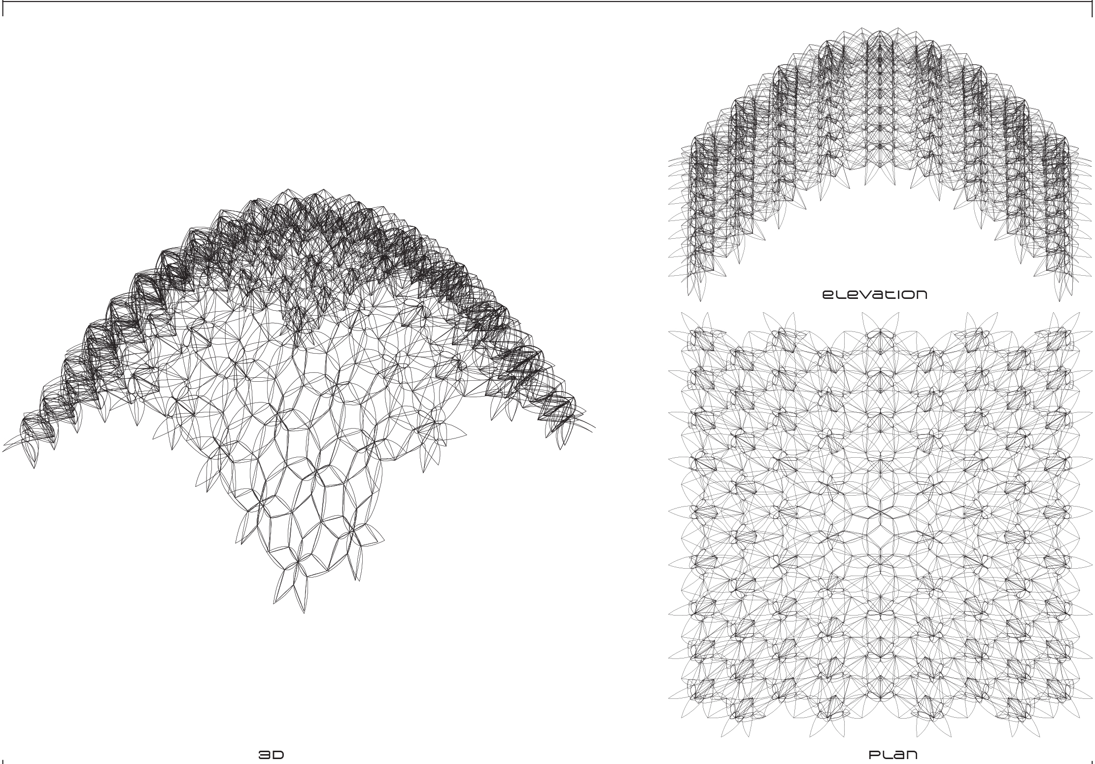
Using a simple elastic lashing system to construct a hypar module binds all intersections together whilst allowing rotational movement. The rotational movement at any given intersection is proportionally distributed to all others. This combined with the elasticity of the joints means that the module has elastic potential energy (spring-like properties) therefore an array of many modules can adopt the same elastic properties.
The system can be scaled, shaped, locked and adapted to suit programmatic requirements.
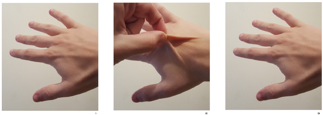
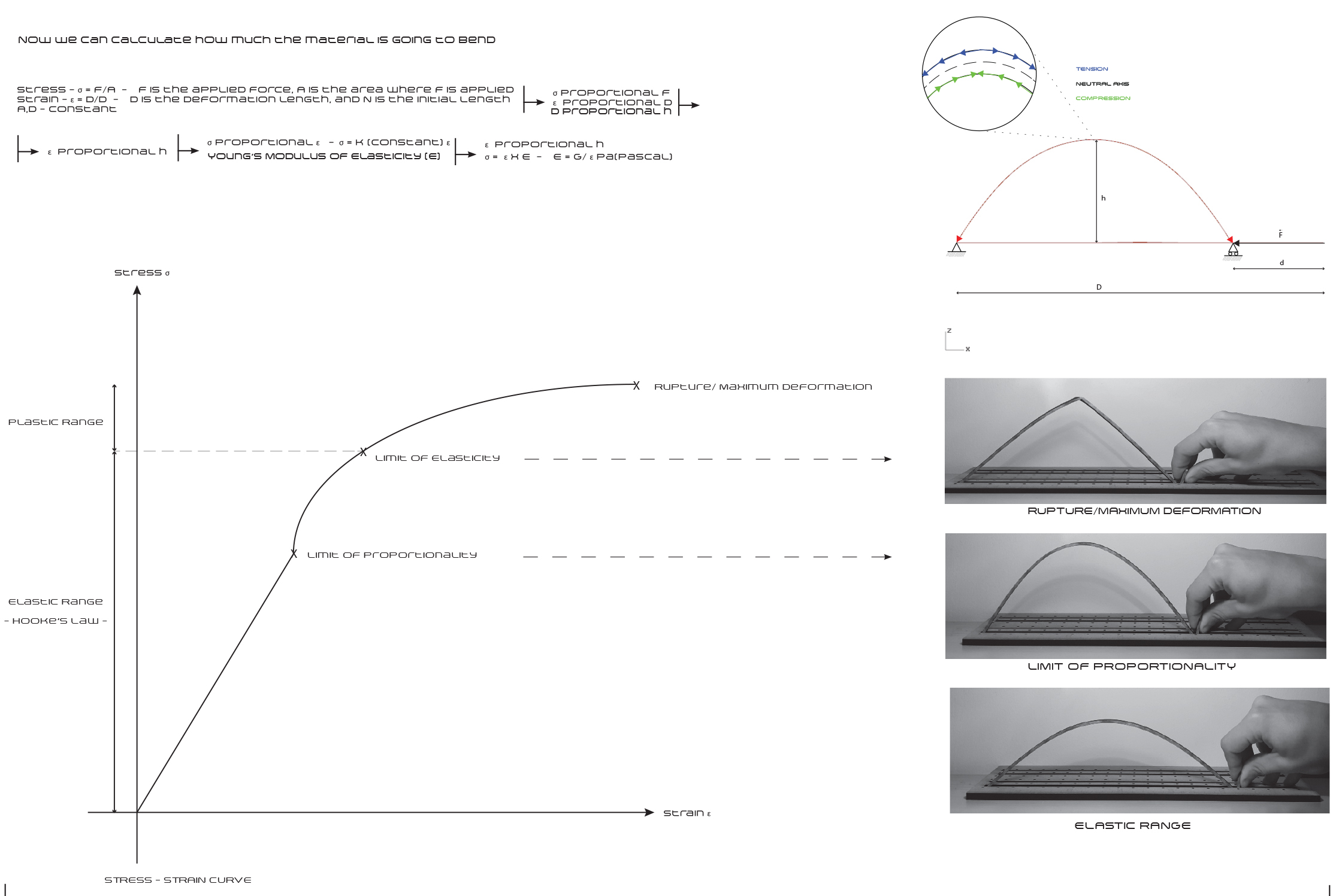
In physics, elasticity (from Greek ἐλαστός “ductible”) is the ability of a body to resist a distorting influence or stress and to return to its original size and shape when the stress is removed.
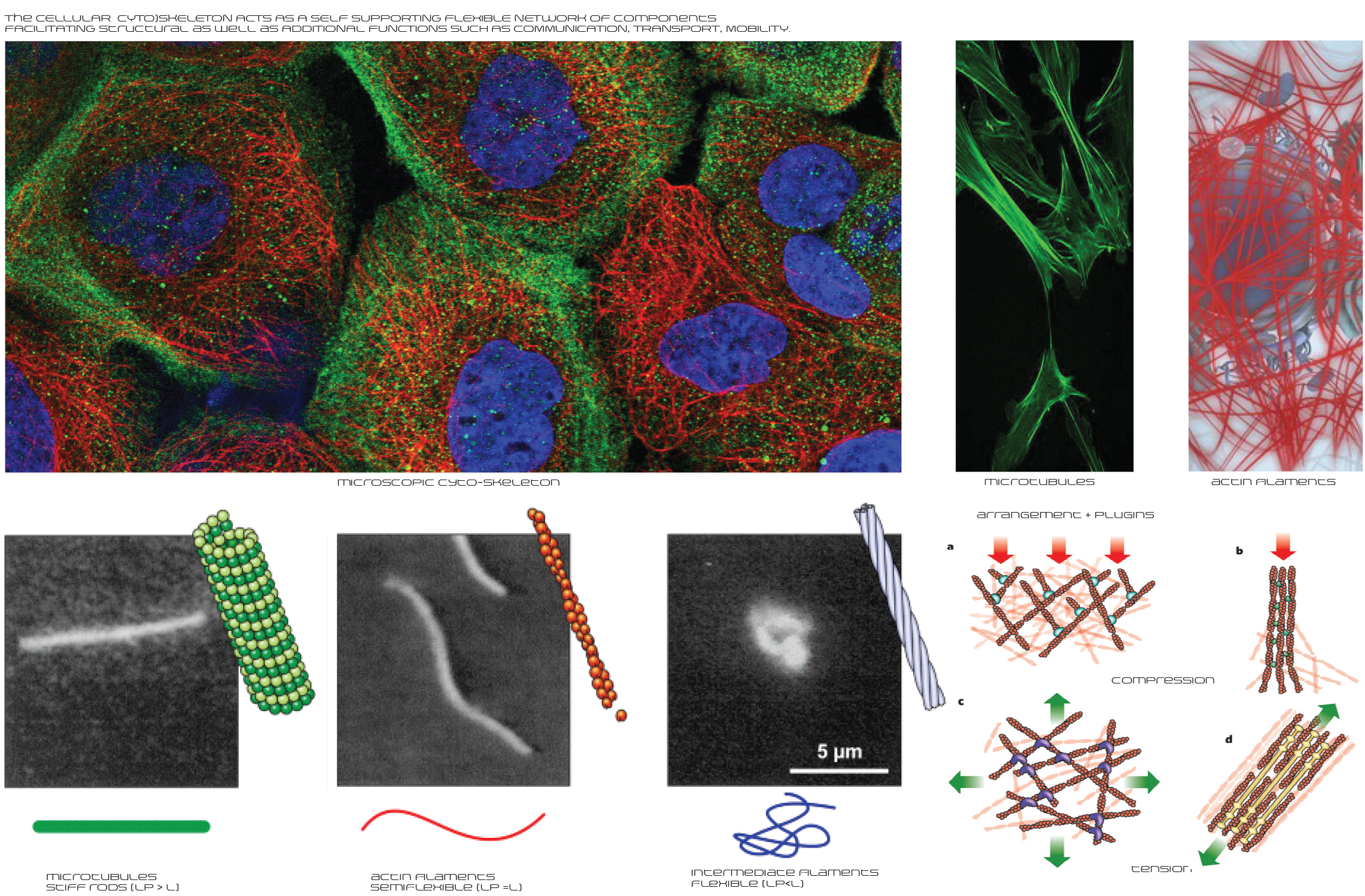
This can be explained looking closer at the components which form the cytoskeleton – the cellular structure – formed of elastic and semi-elastic arrangements of proteins, which are adaptable to the cell’s requirements. Not only do they hold the structural integrity of the cell, but they also also perform functions of communication, transport combined with other “plug-in” proteins, whilst elastically responding to external forces or stimuli.
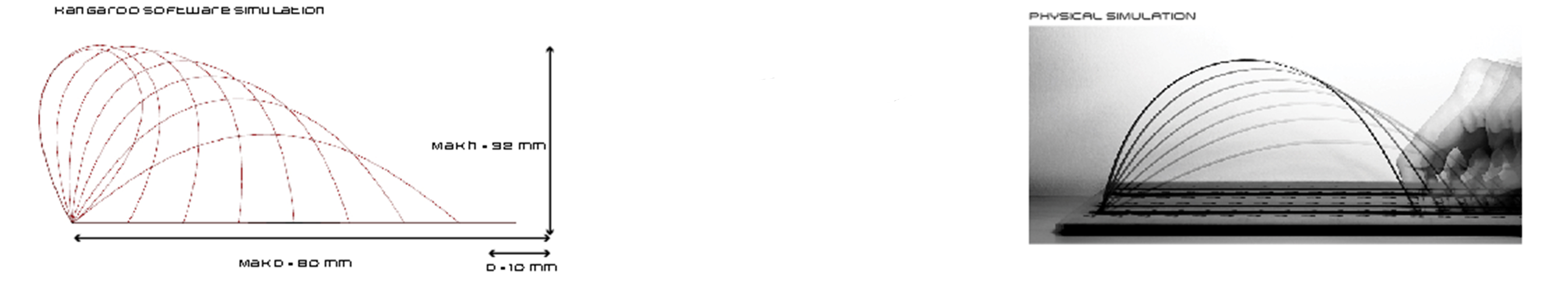
Elastic bending is used in both natural as well as man-made environments, expanding surfaces and volumes of various deployable structures.
The force responsible for elastic bending can be described in terms of the amount of deformation (strain) resulting from a given stress, a ratio known as Young’s Modulus. Hooke’s Law adds that the force responsible with restoring the initial shape of a bent material is proportional to the amount of stretch.
Using the formulas given by Young’s Modulus and Hooke’s Law, we can determine how much a certain material will bend when a force is applied to it.
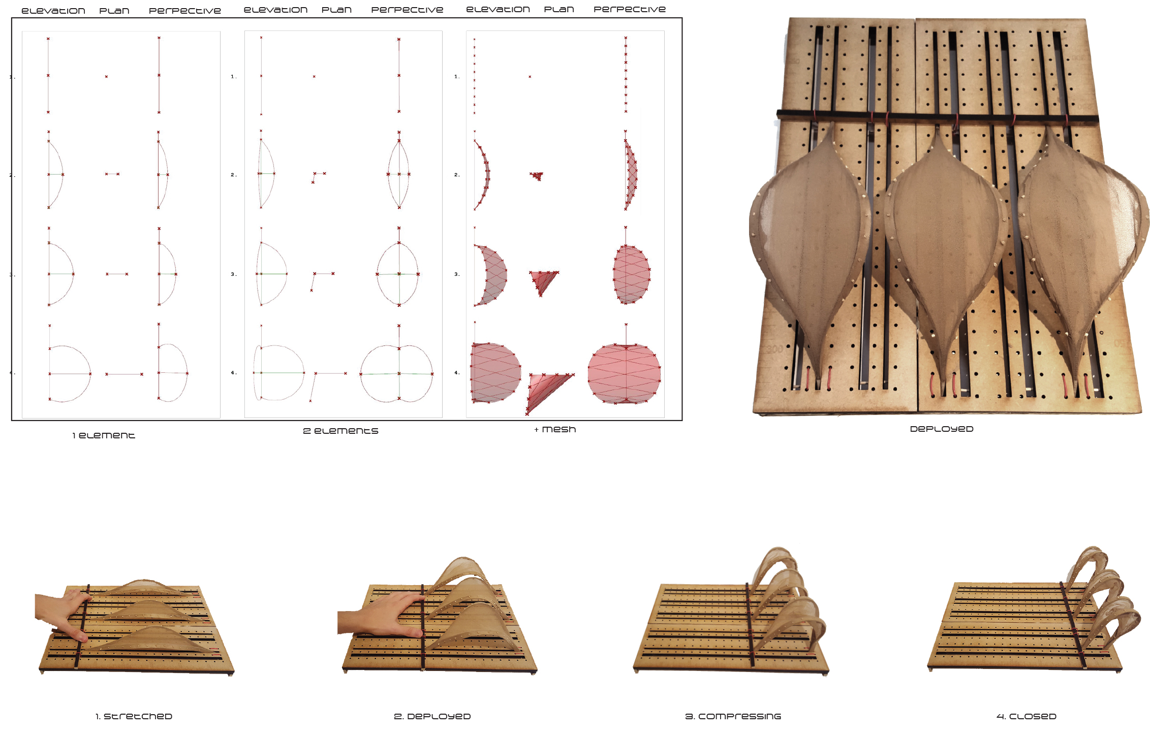
Deploying structures using bending is a space and construction time saving method of producing structural elements which mimic the behaviour of natural systems.
.
After the structure is deployed, equilibrium of forces is required in order to keep the structure open and usable.
This can either be achieved by combining bending elements with meshes,
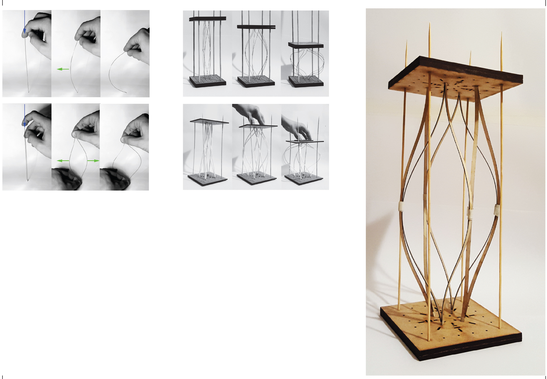
or by using the acting forces of bending elements against the reacting forces of other bending elements in both 2D and 3D.
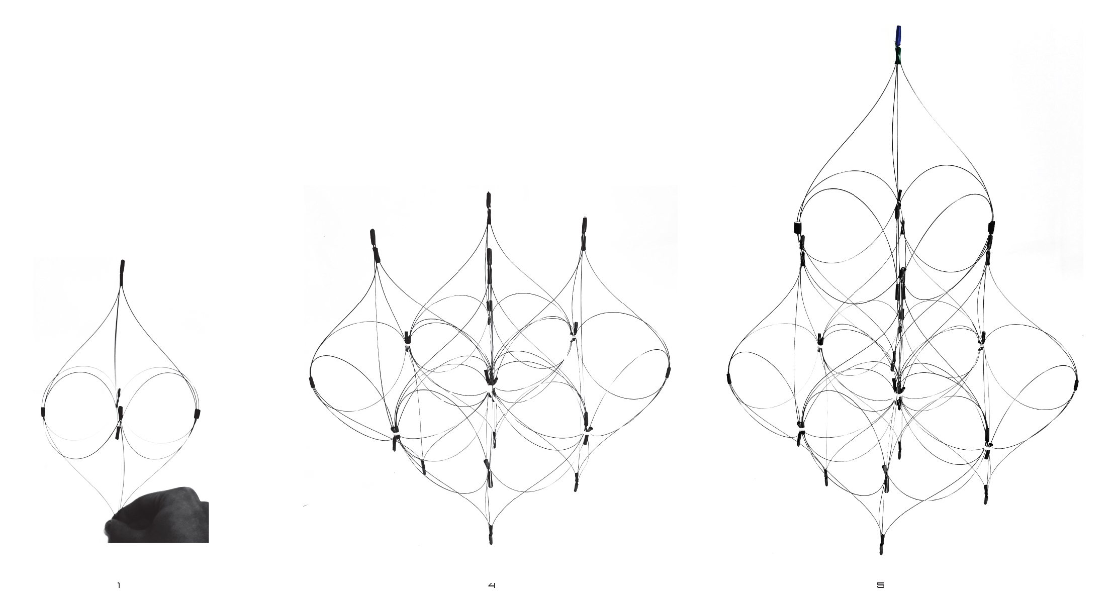
Using these principles of acting forces vs. reacting forces, an elastic module in equilibrium is created, which can be stacked using its geometry to achieve various configurations.
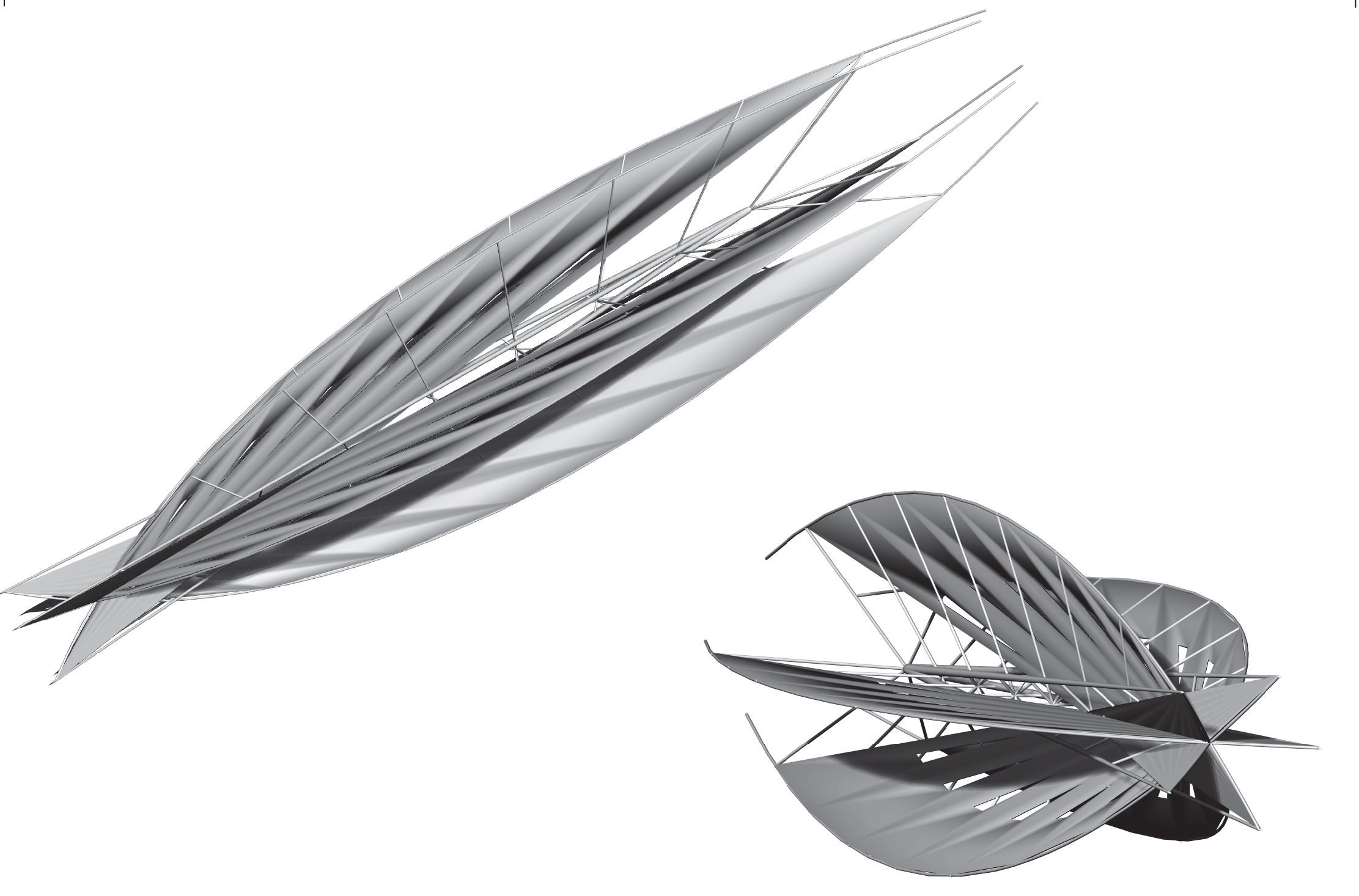
Furthermore, using the same principles, a larger module is created containing groups of elements producing forces acting and reacting against each other, in order to achieve equilibrium.
However, due to the elastic properties of the newly formed module, the structure can bend and morph shape without losing integrity or equilibrium, in order to form various shapes, or respond to or external factors or users requirements, similarly to the cytoskeleton initially studied.
A deployable structure includes an enclosed mechanical linkage capable of transformation between expanded and collapsed configurations while maintaining its shape.
These types of structures have the advantage of creating versatile, modulated spaces, with easy and fast assembly which generate benefits such as adaptability, flexibility and space transformation.
Charles Hoberman pioneered a type of deployable structure based on curved scissor pairs as seen in his Hoberman sphere. The unfolding structure resembles an expanding geodesic sphere which can reach a size up to five times larger than the initial one. It consists of six loop assemblies (or great circles), each made of 60 elements which fold and unfold in a scissor-like motion.
Hoberman Sphere by Charles Hoberman
A loop assembly is formed of at least three scissors-pairs, at least two of the pairs comprising two identical rigid angulated strut elements, each having a central and two terminal pivot points with centres which do not lie in a straight line, each strut being pivotally joined to the other of its pair by their central pivot points. The terminal pivot points of each of the scissors-pairs are pivotally joined to the terminal pivot points of the adjacent pair such that both scissors-pairs lie essentially in the same plane.
Regular curved scissor-pairs in motion
When this loop is folded and unfolded certain critical angles are constant and unchanging. These unchanging angles allow for the overall geometry of structure to remain constant as it expands or collapses.
Regular and irregular curved scissor-pairs in motion
The above diagrams show a closed loop-assembly of irregular scissors pairs where each scissors-pair is pivotally joined by its two pairs of terminal pivot points to the terminal pivot points of its two adjacent scissors-pairs. This loop-assembly is an approximation of a polygon in the sense that the distances between adjacent central pivot points are equal to the corresponding lengths of the sides of the polygon. Further, the angles between the lines joining adjacent central pivot points with other similarly formed lines in the assembly are equal to the corresponding angles in the polygon.
The beams forming scissor-pairs can be of almost any shape, providing that the three connection points form a triangle. The angle of the apex would dictate the number of scissor-pairs that can be linked together to form a closed loop.
Scissor-pairs of varying morphologies
My physical experiments started with materials that would allow a degree of bending and torsion in order to test the limits of the system. Using polypropylene for the angular beams and metal screws for the joints, I created these playful models that bend as they expand and contract.
Later I started using MDF for the beams as well as joints and noticed that a degree of bending was present in the expanded state of the larger circle.
After using curved scissor pairs of the same angle to form closed linkages, I decided to combine two types of scissors and vary the proportion between the elements to achieve a loop which would offer the highest ratio between the expanded and contracted state.
900 curved scissors loops
900 curved scissors with linear scissors loops
The above diagrams show a combination of 900 curved scissors with linear (1800) scissors to form rectangles that expand and contract. The length of the 900 beam was gradually increasedand by measuring the diagonalsof the most expanded and most contracted forms, I obtained the following ratios for the three rectangles:
R1 = 0.87
R2 = 0.67
R3 = 0.64
By keeping the curved scissor with the best ratio, I created three more rectangles, this time by varying the length of the linear beam. The following ratios were obtained:
R1 = 0.64
R2 = 0.59
R3 = 0.67
900 curved scissors with linear scissors loops
I then took the linkage with the best ratio of 0.59 and rotated it 900 to form a cube which expands and contracts.
Combined linkage cubes
The change of state from open to closed is visually attractive and could have the potential of creating spaces that are transitional.If more linear scissors are placed between the 900 scissors, a better contraction ratio is obtained.
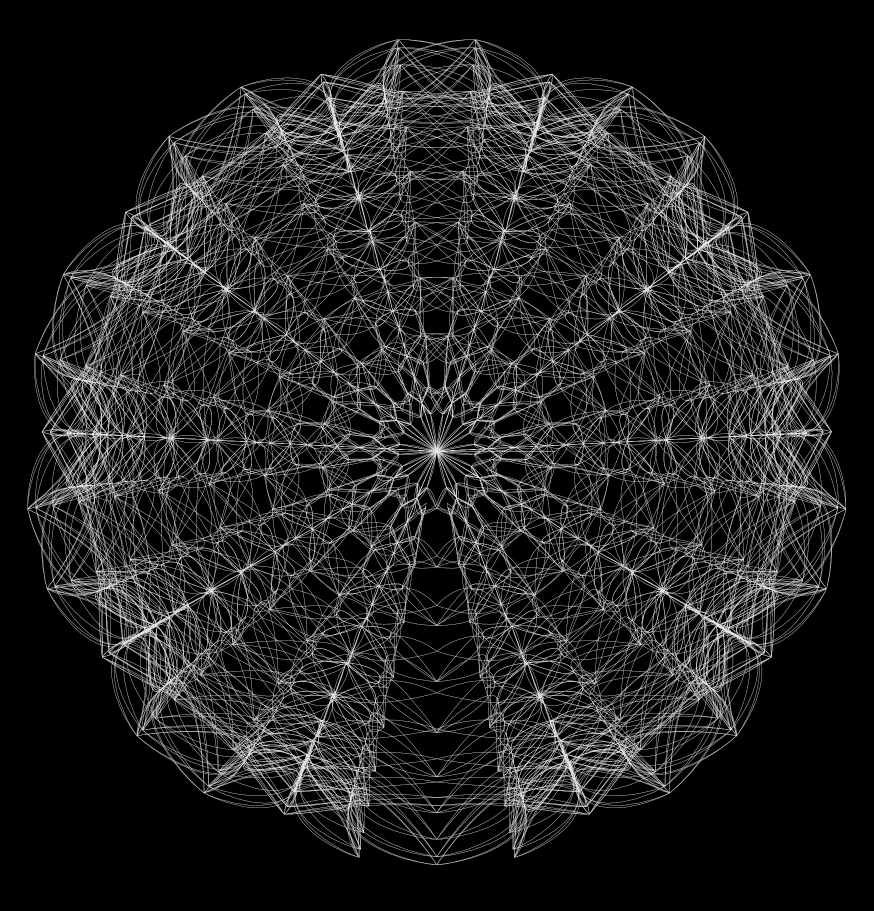
the Spirograph is a geometric drawing toy that produces a variety of mathematical roulette curves.
it was invented and developed by the English engineer Denys Fisher. in 1960, Fisher set up his own company, Denys Fisher Engineering, in Leeds. the company won a contract with NATO to supply springs and precision component for its 20 mm cannon. between 1962 and 1964 he developed various drawing machines, eventually producing a prototype Spirograph.
Spirograph was patented in 16 countries and was first sold in the UK in 1965. a year later, Fisher licensed Spirograph to Kenner Products in the United States. in 1967 Spirograph was chosen as the UK Toy of the Year.
it consisted of different-sized plastic rings, with gear teeth on both the inside and outside of their circumferences. they were pinned to a cardboard backing with pins and any of several provided gearwheels, which had holes provided for a ballpoint pen, could be spun around to make geometric shapes on paper. later, the Super-Spirograph consisted of a set of plastic gears and other interlocking shape-segments such as rings, triangles, or straight bars.
the curves produced by the Spirograph toy are technically known as hypotrochoids and epitrochoids.
a hypotrochoid curve is traced by a point attached to a circle of radius r rolling around the inside of a fixed circle of radius R, where the point is a distance d from the centre of the interior circle.
The parametric equations for a hypotrochoid are:
where θ is the angle formed by the horizontal and the centre of the rotating circle.
a epitrochoid curve is traced by a point attached to a circle of radius r rolling around the outside of a fixed circle of radius R, where the point is a distance d from the center of the exterior circle.
The parametric equations for a epitrochoid are:
where θ is the angle formed by the horizontal and the centre of the rotating circle.


 The Helicoid
 A parametrized helicoid. The function (u,v)=(ucosv,usinv,v) parametrizes a helicoid when (u,v) E D, where D is the rectangle [0,1]Å~[0,2]. The region D, shown as the rectangle in the first panel. The region D is divided into small rectangles which are mapped to “curvy rectangles” on the surface. You can click any of the borders of the small rectangles to highlight a curve where one of the variables is constant. Vertical lines in the rectangle D represent curves where u is constant; these correspond to curves that spiral up the helicoid. Horizontal lines in the rectangle D represent curves where v is constant; these correspond to lines that cut across the helicoid.
 The research into helicoid surfaces led to experiments with Curved Crease Origami. Experiments were done by cutting different shaped components out of the folded helicoid and connecting them together.


 Physical model


 If more linear scissors are placed between the 900 scissors, a better contraction ratio is obtained.