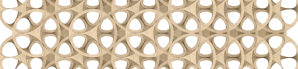
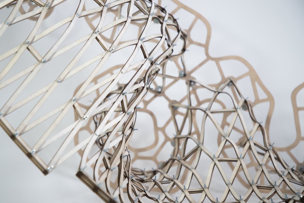
The initial aspiration of the project was to produce a method of simplifying the construction of the 5 regular platonic solids (Tetrahedron, Cube, Octahedron, Dodecahedron and Icosahedron) using only bend active timber and simple bolted connections, eliminating the need for complex nodal connections as seen in geodesic dome construction and other compound angle connections.
Bend active timber being the main research topic, the structural capabilities and bending radii of plywood were physically tested incorporating the several thicknesses and crucially the direction of the bend either being parallel or perpendicular to the grain, resulting in an informative results matrix.
Digital explorations were undertaken for each of the platonic solids creating various sized volumetric frame structures. The resultant sizes were due to each component being constrained to fit on a standard 2440x1220mm plywood sheet and the resultant bending radius
Following physical investigations of each, the cube was taken forward as it was; more efficient in terms of material usage, easier method of assembly comparatively and unintentionally produced a deployable mechanism similar to the famous Hoberman’s sphere.
The system utilizes identical components meaning the fabrication process can be quickly and easily performed using a CNC machine, with assembling being intuitive, not requiring different parts or specialised assembly instructions. The components were cut using my own CNC and were then simply assembled by hand using bolted connections to create the skeletal frame. Assembly was extremely quick, from flat components to finished volumetric module taking only 20 minutes.
The pre-fabricated modules can then be replicated and scaled, to suit various habitable typologies a community would need or can be used individually as a deployable shelter for the homeless/emergency relief.
Regarding my previous entries, it can be difficult to see how any of this has to do with architecture. In fact I know a few people who think studying fractals is pointless.
Admittedly I often struggle to explain to people what fractals are, let alone how they can influence the way buildings look. However, I believe that this post really sheds light on how these kinds of studies may directlyinfluence and enhance our understanding (and perhaps even the future) of our built environment.
On a separate note, I heard that a member of the architectural academia said “forget biomimicry, it doesn’t work.”
Firstly, I’m pretty sure Frei Otto would be rolling over in his grave.
Secondly, if someone thinks that biomimicry is useless, it’s because they don’t really understand what biomimicry is. And I think the same can be said regarding the study of fractals. They are closely related fields of study, and I wholeheartedly believe they are fertile grounds for architectural marvels to come.
7.0 Introduction to Shells
As far as classification goes, shells generally fall under the category of two-dimensional shapes. They are defined by a curved surface, where the material is thin in the direction perpendicular to the surface. However, assigning a dimension to certain shells can be tricky, since it kinda depends on how zoomed in you are.
A strainer is a good example of this – a two-dimensional gridshell. But if you zoom in, it is comprised of a series of woven, one-dimensional wires. And if you zoom in even further, you see that each wire is of course comprised of a certain volume of metal.
This is a property shared with many fractals, where their dimension can appear different depending on the level of magnification. And while there’s an infinite variety of possible shells, they are (for the most part) categorizable.
7.1 – Single Curved Surfaces
Analytic geometry is created in relation to Cartesian planes, using mathematical equations and a coordinate systems. Synthetic geometry is essentially free-form geometry (that isn’t defined by coordinates or equations), with the use of a variety of curves called splines. The following shapes were created via Synthetic geometry, where we’re calling our splines ‘u’ and ‘v.’
Uniclastic: Barrel Vault (Cylindrical paraboloid)
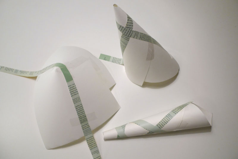
These curves highlight each dimension of the two-dimensional surface. In this case only one of the two ‘curves’ is actually curved, making this shape developable. This means that if, for example, it was made of paper, you could flatten it completely.
Uniclastic: Conoid (Conical paraboloid)
In this case, one of them grows in length, but the other still remains straight. Since one of the dimensions remains straight, it’s still a single curved surface – capable of being flattened without changing the area. Singly curved surfaced may also be referred to as uniclastic or monoclastic.
7.2 – Double Curved Surfaces
These can be classified as synclastic or anticlastic, and are non-developable surfaces. If made of paper, you could not flatten them without tearing, folding or crumpling them.
Synclastic: Dome (Elliptic paraboloid)
In this case, both curves happen to be identical, but what’s important is that both dimensions are curving in the same direction. In this orientation, the dome is also under compression everywhere.
The surface of the earth is double curved, synclastic – non-developable. “The surface of a sphere cannot be represented on a plane without distortion,” a topic explored by Michael Stevens: https://www.youtube.com/watch?v=2lR7s1Y6Zig
Anticlastic: Saddle (Hyperbolic paraboloid)
This one was formed by non-uniformly sweeping a convex parabola along a concave parabola. It’s internal structure will behave differently, depending on the curvature of the shell relative to the shape. Roof shells have compressive stresses along the convex curvature, and tensile stress along the concave curvature.
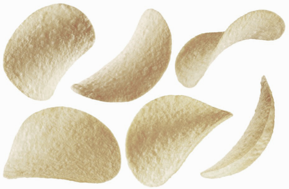
Kellogg’s potato and wheat-based stackable snack
Here is an example of a beautiful marriage of tensile and compressive potato and wheat-based anticlastic forces. Although I hear that Pringle cans are diabolically heinous to recycle, so they are the enemy.
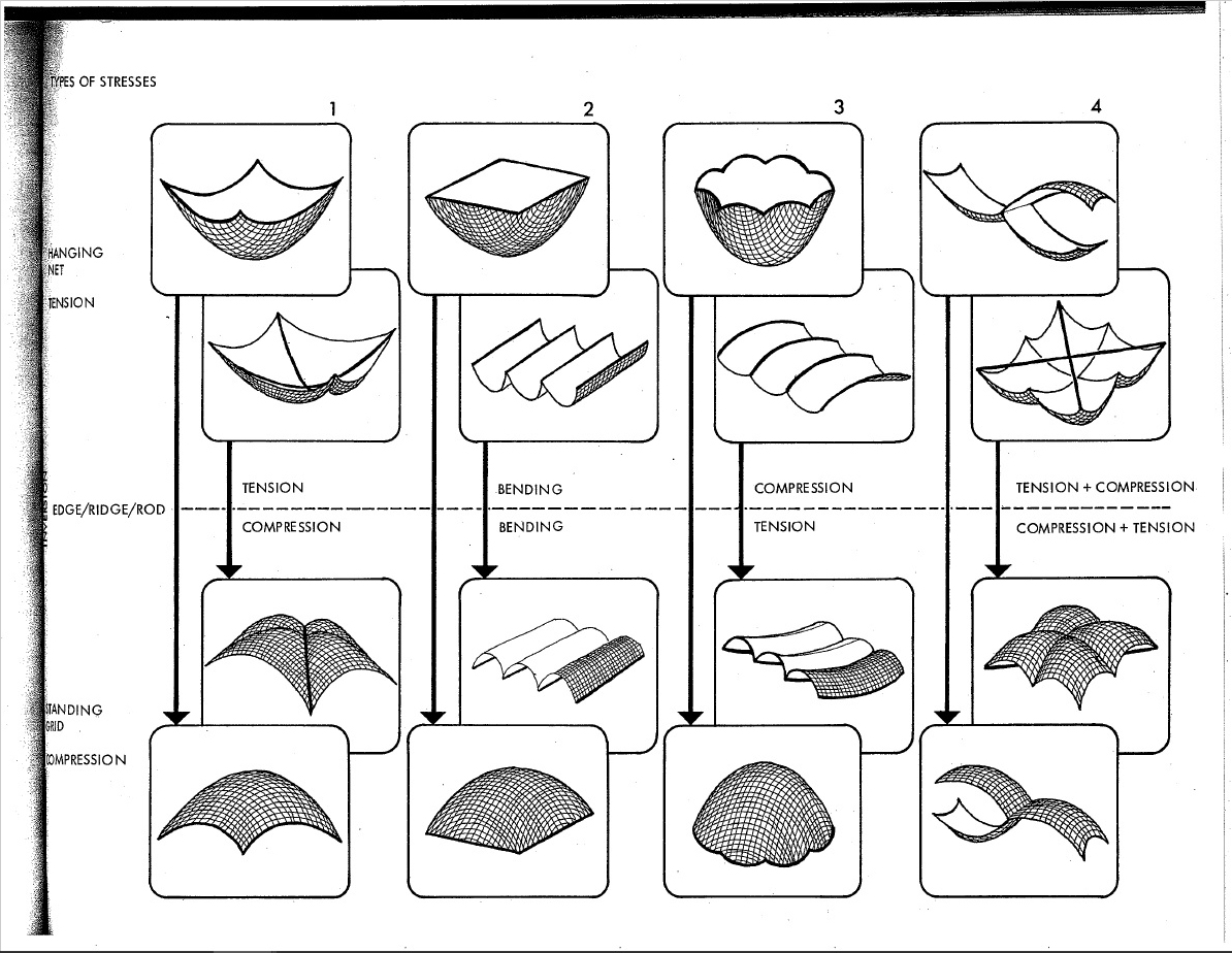
Structural Behaviour of Basic Shells [Source: IL 10 – Institute for Lightweight Structures and Conceptual Design]
7.3 – Translation vs Revolution
In terms of synthetic geometry, there’s more than one approach to generating anticlastic curvature:
Hyperbolic Paraboloid: Straight line sweep variation
This shape was achieved by sweeping a straight line over a straight path at one end, and another straight path at the other. This will work as long as both rails are not parallel. Although I find this shape perplexing; it’s double curvature that you can create with straight lines, yet non-developable, and I can’t explain it..
Ruled Surface & Surface of Revolution (Circular Hyperboloid)
The ruled surface was created by sliding a plane curve (a straight line) along another plane curve (a circle), while keeping the angle between them constant. The surfaces of revolution was simply made by revolving a plane curve around an axis. (Surface of translation also exist, and are similar to ruled surfaces, only the orientation of the curves is kept constant instead of the angle.)
Hyperboloid Generation [Source:Wikipedia]
The hyperboloid has been a popular design choice for (especially nuclear cooling) towers. It has excellent tensile and compressive properties, and can be built with straight members. This makes it relatively cheap and easy to fabricate relative to it’s size and performance.
These are singly curved curves, although that does sound confusing. A simple way to understand what geodesic curves are, is to give them a width. As previously explored, we know that curves can inhabit, and fill, two-dimensional space. However, you can’t really observe the twists and turns of a shape that has no thickness.
Conic Plank Lines (Source: The Geometry of Bending)
A ribbon is essentially a straight line with thickness, and when used to follow the curvature of a surface (as seen above), the result is a plank line. The term ‘plank line’ can be defined as a line with an given width (like a plank of wood) that passes over a surface and does not curve in the tangential plane, and whose width is always tangential to the surface.
Since one-dimensional curves do have an orientation in digital modeling, geodesic curves can be described as the one-dimensional counterpart to plank lines, and can benefit from the same definition.
For simplicity, here’s a basic grid set up on a flat plane:
Basic geodesic curves on a plane
We start by defining two points anywhere along the edge of the surface. Then we find the geodesic curve that joins the pair. Of course it’s trivial in this case, since we’re dealing with a flat surface, but bear with me.
Initial set of curves
We can keep adding pairs of points along the edge. In this case they’re kept evenly spaced and uncrossing for the sake of a cleaner grid.
Addition of secondary set of curves
After that, it’s simply a matter of playing with density, as well as adding an additional set of antagonistic curves. For practicality, each set share the same set of base points.
Grid with independent sets
He’s an example of a grid where each set has their own set of anchors. While this does show the flexibility of a grid, I think it’s far more advantageous for them to share the same base points.
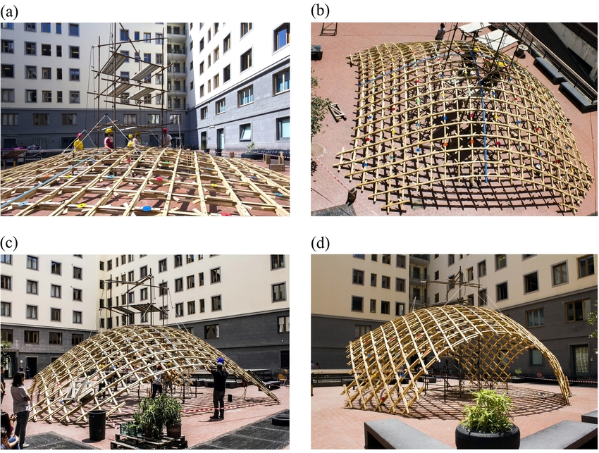
8.2 – Basic Gridshells
The same principle is then applied to a series of surfaces with varied types of curvature.
Uniclastic: Barrel Vault Geodesic Gridshell
First comes the shell (a barrel vault in this case), then comes the grid. The symmetrical nature of this surface translates to a pretty regular (and also symmetrical) gridshell. The use of geodesic curves means that these gridshells can be fabricated using completely straight material, that only necessitate single curvature.
Uniclastic: Conoid Geodesic Gridshell
The same grid used on a conical surface starts to reveal gradual shifts in the geometry’s spacing. The curves always search for the path of least resistance in terms of bending.
Synclastic: Dome Geodesic Gridshell
This case illustrates the nature of geodesic curves quite well. The dome was free-formed with a relatively high degree of curvature. A small change in the location of each anchor point translates to a large change in curvature between them. Each curve looks for the shortest path between each pair (without leaving the surface), but only has access to single curvature.
Anticlastic: Saddle Geodesic Gridshell
Structurally speaking, things get much more interesting with anticlastic curvature. As previously stated, each member will behave differently based on their relative curvature and orientation in relation to the surface. Depending on their location on a gridshell, plank lines can act partly in compression and partly in tension.
On another note:
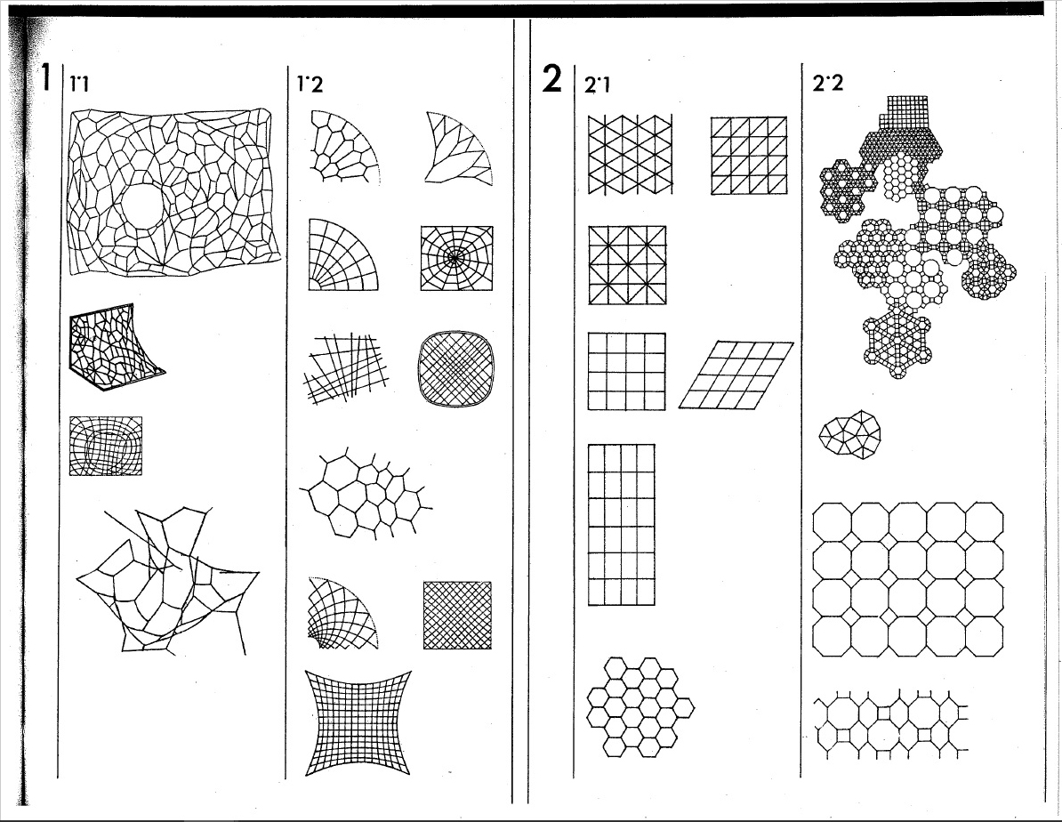
While geodesic curves make it far more practical to fabricate shells, they are not a strict requirement. Using non-geodesic curves just means more time, money, and effort must go into the fabrication of each component. Furthermore, there’s no reason why you can’t use alternate grid patterns. In fact, you could use any pattern under the sun – any motif your heart desires (even tessellated puppies.)
Alternate Gridshell Patterns [Source: IL 10 – Institute for Lightweight Structures and Conceptual Design]
Here are just a few of the endless possible pattern. They all have their advantages and disadvantages in terms of fabrication, as well as structural potential.
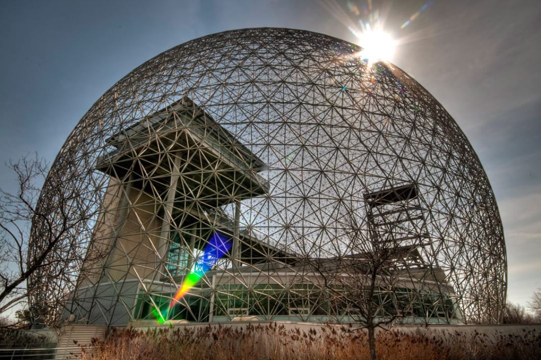
Biosphere Environment Museum – Canada
Gridshells with large amounts of triangulation, such as Buckminster Fuller’s geodesic spheres, typically perform incredibly well structurally. These structure are also highly efficient to manufacture, as their geometry is extremely repetitive.
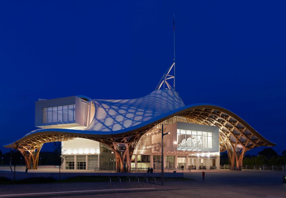
Centre Pompidou-Metz – France
Gridshells with highly irregular geometry are far more challenging to fabricate. In this case, each and every piece had to be custom made to shape; I imagine it must have costed a lot of money, and been a logistical nightmare. Although it is an exceptionally stunning piece of architecture (and a magnificent feat of engineering.)
8.3 – Gridshell Construction
In our case, building these shells is simply a matter of converting the geodesic curves into planks lines.
Hyperbolic Paraboloid: Straight Line Sweep Variation With Rotating Plank Line Grid
The whole point of using them in the first place is so that we can make them out of straight material that don’t necessitate double curvature. This example is rotating so the shape is easier to understand. It’s grid is also rotating to demonstrate the ease at which you can play with the geometry.
Hyperbolic Paraboloid: Flattened Plank Lines With Junctions
This is what you get by taking those plank lines and laying them flat. In this case both sets are the same because the shell happens to the identicall when flipped. Being able to use straight material means far less labour and waste, which translates to faster, and or cheaper, fabrication.
An especially crucial aspect of gridshells is the bracing. Without support in the form of tension ties, cable ties, ring beams, anchors etc., many of these shells can lay flat. This in and of itself is pretty interesting and does lends itself to unique construction challenges and opportunities. This isn’t always the case though, since sometimes it’s the geometry of the joints holding the shape together (like the geodesic spheres.) Sometimes the member are pre-bent (like Pompidou-Metz.) Although pre-bending the timber kinda strikes me as cheating thought.. As if it’s not a genuine, bona fide gridshell.
Toledo Gridshell 2.0. Construction Process [source: Timber gridshells – Numerical simulation, design and construction of a full scale structure]
This is one of the original build method, where the gridshell is assembled flat, lifted into shape, then locked into place.
9.0 Form Finding
Having studied the basics makes exploring increasingly elaborate geometry more intuitive. In principal, most of the shells we’ve looked are known to perform well structurally, but there are strategies we can use to focus specifically on performance optimization.
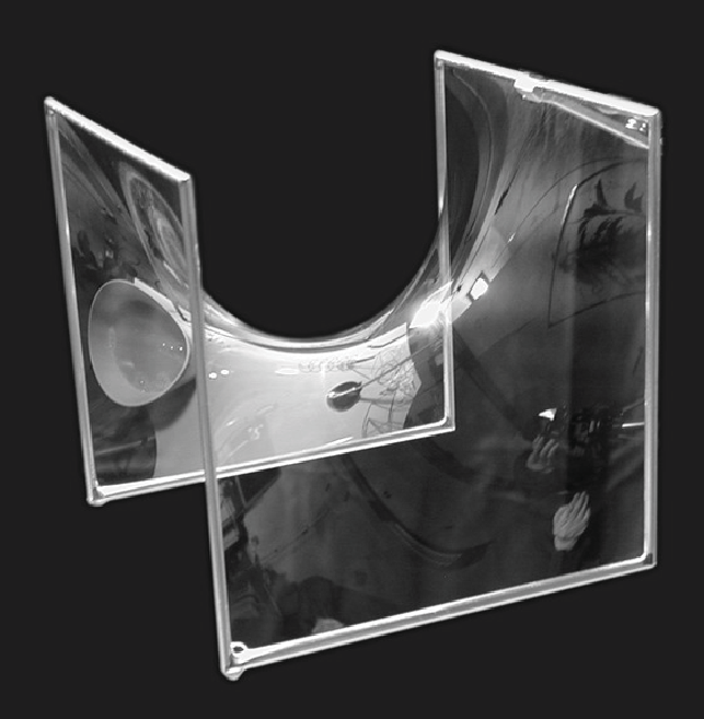
9.0 – Minimal Surfaces
These are surfaces that are locally area-minimizing – surfaces that have the smallest possible area for a defined boundary. They necessarily have zero mean curvature, i.e. the sum of the principal curvatures at each point is zero. Soap bubbles are a great example of this phenomenon.
Hyperbolic Paraboloid Soap Bubble [Source: Serfio Musmeci’s “Froms With No Name” and “Anti-Polyhedrons”]Soap film inherently forms shapes with the least amount of area needed to occupy space – that minimize the amount of material needed to create an enclosure. Surface tension has physical properties that naturally relax the surface’s curvature.
Kangaroo2 Physics: Surface Tension Simulation
We can simulate surface tension by using a network of curves derived from a given shape. Applying varies material properties to the mesh results in a shape that can behaves like stretchy fabric or soap. Reducing the rest length of each of these curves (while keeping the edges anchored) makes them pull on all of their neighbours, resulting in a locally minimal surface.
Here are a few more examples of minimal surfaces you can generate using different frames (although I’d like stress that the possibilities are extremely infinite.) The first and last iterations may or may not count, depending on which of the many definitions of minimal surfaces you use, since they deal with pressure. You can read about it in much greater detail here: https://tinyurl.com/ya4jfqb2
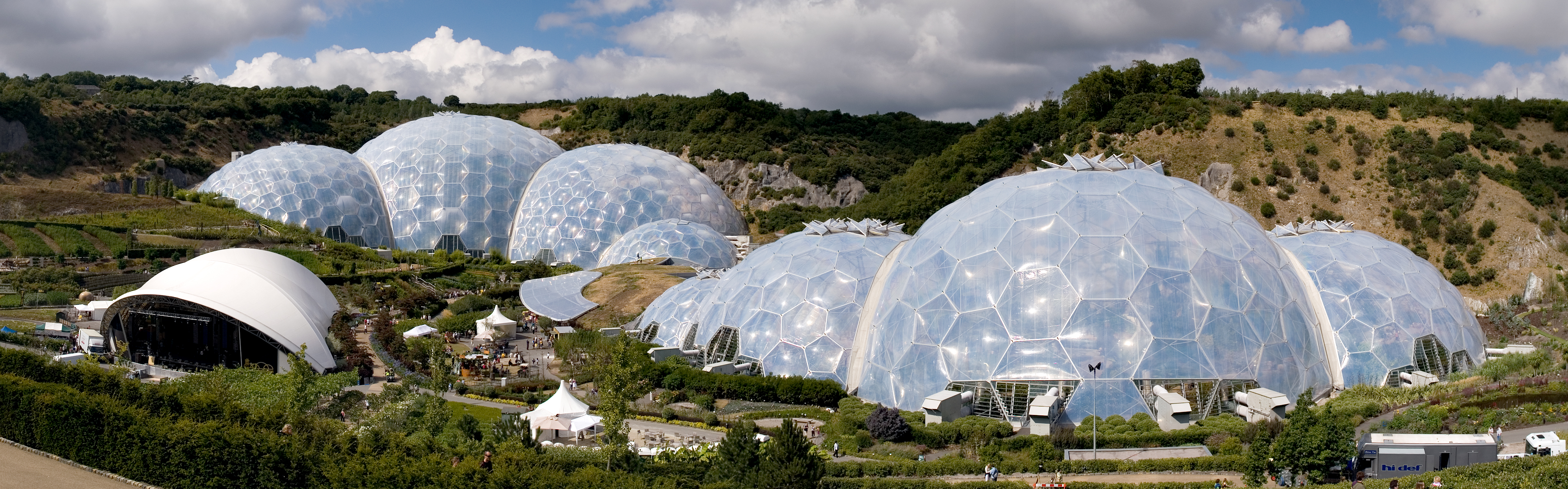
The Eden Project – United Kingdom
Here we have one of the most popular examples of minimal surface geometry in architecture. The shapes of these domes were derived from a series of studies using clustered soap bubbles. The result is a series of enormous shells built with an impressively small amount of material.
Triply periodic minimal surfaces are also a pretty cool thing (surfaces that have a crystalline structure – that tessellate in three dimensions):
Another powerful method of form finding has been to let gravity dictate the shapes of structures. In physics and geometry, catenary (derived from the Latin word for chain) curves are found by letting a chain, rope or cable, that has been anchored at both end, hang under its own weight. They look similar to parabolic curves, but perform differently.
Kangaroo2 Physics: Catenary Model Simulation
A net shown here in magenta has been anchored by the corners, then draped under simulated gravity. This creates a network of hanging curves that, when converted into a surface, and mirrored, ultimately forms a catenary shell. This geometry can be used to generate a gridshell that performs exceptionally well under compression, as long as the edges are reinforced and the corners are braced.
While I would be remiss to not mention Antoni Gaudí on the subject of catenary structure, his work doesn’t particularly fall under the category of gridshells. Instead I will proceed to gawk over some of the stunning work by Frei Otto.
Of course his work explored a great deal more than just catenary structures, but he is revered for his beautiful work on gridshells. He, along with the Institute for Lightweight Structures, have truly been pioneers on the front of theoretical structural engineering.
9.3 – Biomimicry in Architecture
There are a few different terms that refer to this practice, including biomimetics, bionomics or bionics. In principle they are all more or less the same thing; the practical application of discoveries derived from the study of the natural world (i.e. anything that was not caused or made by humans.) In a way, this is the fundamental essence of the scientific method: to learn by observation.
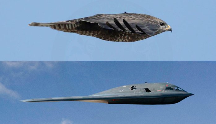
Example of Biomimicry
Frei Otto is a fine example of ecological literacy at its finest. A profound curiosity of the natural world greatly informed his understanding of structural technology. This was all nourished by countless inquisitive and playful investigations into the realm of physics and biology. He even wrote a series of books on the way that the morphology of bird skulls and spiderwebs could be applied to architecture called Biology and Building. His ‘IL‘ series also highlights a deep admiration of the natural world.
Of course he’s the not the only architect renown their fascination of the universe and its secrets; Buckminster Fuller and Antoni Gaudí were also strong proponents of biomimicry, although they probably didn’t use the term (nor is the term important.)
Gaudí’s studies of nature translated into his use of ruled geometrical forms such as hyperbolic paraboloids, hyperboloids, helicoids etc. He suggested that there is no better structure than the trunk of a tree, or a human skeleton. Forms in biology tend to be both exceedingly practical and exceptionally beautiful, and Gaudí spent much of his life discovering how to adapt the language of nature to the structural forms of architecture.
Fractals were also an undisputed recurring theme in his work. This is especially apparent in his most renown piece of work, the Sagrada Familia. The varying complexity of geometry, as well as the particular richness of detail, at different scales is a property uniquely shared with fractal nature.
Antoni Gaudí and his legacy are unquestionably one of a kind, but I don’t think this is a coincidence. I believe the reality is that it is exceptionally difficult to peruse biomimicry, and especially fractal geometry, in a meaningful way in relation to architecture. For this reason there is an abundance of superficial appropriation of organic, and mathematical, structures without a fundamental understanding of their function. At its very worst, an architect’s approach comes down to: ‘I’ll say I got the structure from an animal. Everyone will buy one because of the romance of it.”
That being said, modern day engineers and architects continue to push this envelope, granted with varying levels of success. Although I believe that there is a certain level of inevitability when it comes to how architecture is influenced by natural forms. It has been said that, the more efficient structures and systems become, the more they resemble ones found in nature.
Euclid, the father of geometry, believed that nature itself was the physical manifestation of mathematical law. While this may seems like quite a striking statement, what is significant about it is the relationship between mathematics and the natural world. I like to think that this statement speaks less about the nature of the world and more about the nature of mathematics – that math is our way of expressing how the universe operates, or at least our attempt to do so. After all, Carl Sagan famously suggested that, in the event of extra terrestrial contact, we might use various universal principles and facts of mathematics and science to communicate.
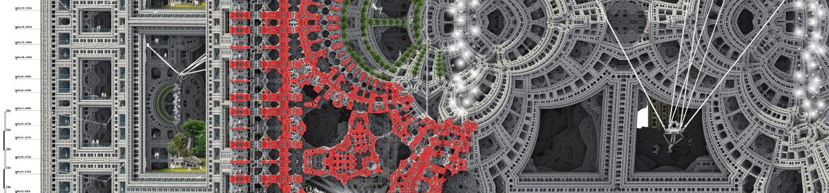
dis/integration[loops], inspired by the composer William Basinski’s seminal works of the same name, explores the limitations of digital processes in our world – and the chaos that can unfold from overreliance on them.
A towering array is assembled from recursive fragments of an inherently destructive process. It explores the tension that exists between the digital and physical realms; challenging an immortal, digital world, the glorious ruin of the analogue realm confronts the perceived perfection of the artificial.
Existing in a state of intended incompleteness, dis/integration[loops] eschews vanity in favour of exhibiting procedural rawness; the power of ruinous accident reveals itself through the tarnishing of idyllic digitalism.
Pressure-laminated plywood modules, form-found through iterative casting experiments, connect to form a pervious, fragmented structure; it’s transcience and impermanence exaggerated as night follows day.
In the same way that Basinski’s fragile recordings were destroyed upon being processed by the human ear, dis/integration[loops] exists in a contented, lush and shimmering state prior to being activated by human presence.
Proximity-controlled LED lighting impregnates the structure. When combined with sounds inspired by those Basinski’s (de)generative process created, this affords a level of animated deconstruction upon activation; visually and sonically, the imperfect presence of humanity causes dis/integration[loops] to be engulfed in chaotic ripples of distortion.
It’s most perfect (yet still decidedly imperfect) state is one in which it lies dormant and peaceful, undiscovered by the presence of people. It experientially disintegrates upon activation.
The fragmented structure exaggerates ever-changing natural light conditions and provides shelter, as well as an intimate, tactile space withi it’s permeable walls.
‘And then as the last crackle faded and the music was no more, I took in my surroundings and looked around at the faces and I was right there with everybody and we were alive.’
dis/integration[loops] is a reminder than everything we encounter eventually falls apart and returns to dust. It challenges the perfect, edited, occularcentrism that blights our social lives, explores the sound of decay, and the beauty that can exist in destruction. It is a meditation on death and loss, and exploration on a theme that some things are better left untouched.
The experience of life – a gradual disintegration – is simultaneously enriched and eroded by the imperfect nature of our encounters; pristine digitalism deserves a tarnished, ruinous quality symbolic of our experiences.
‘and I was right there with everybody and we were alive.’
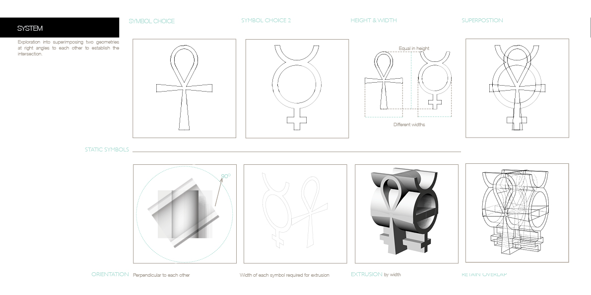
This project is a physical exploration of anamorphosis in three dimensions centred around the theme of duality. It aims to combine two widely recognisable figures into a pavilion that will attract burners, provoke debate, and catalyse interaction.
The theme of this project arose from the realisation that even the most widely recognisable symbols contain multiple layers of meaning and mystery. Social, historical and sometimes even spiritual contexts give a symbol its perceived meaning. For example, while the Christian cross is a symbol of hope it is literally a scaled representation of an ancient torture device – an icon synonymous with good carries with it a darker elucidation. This interpretation led to the emergence of duality as a topic and a title. There are many symbols which have multiple meanings and nuances to those who interpret them.
I began by looking at the Ankh, the Egyptian symbol for life/fertility. The Loop of the Ankh represents the feminine discipline or the womb, while the elongated section represent the masculine discipline or the penis. These two sacred units then come together and form life. This is a perfect representation of man and woman in perfect union. I then was led to study the symbol for mercury, which is used in botany to indicate a flower with both male and female reproductive organs.
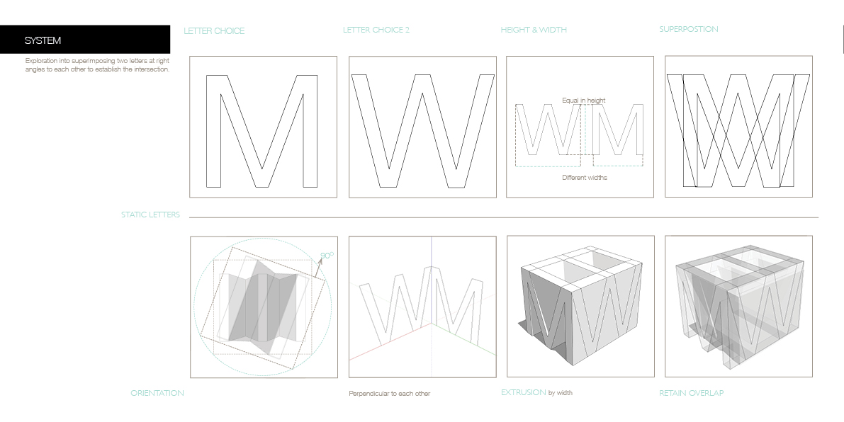
This duality of meaning in symbols led me to the desire to study how I could physically combine other symbols and forms to create one form. Anamorphosis, from the Greek anamorphōsis meaning ‘transformation,’ from ana- ‘back, again’ + morphosis ‘a shaping’, became an interesting opportunity to do just this.
I want to explore this theme using the iconic faces of Donald Trump and Kim Kardashian as instigators. From a random vantage point or even from up close, the subject matter of the piece is evidently unclear, the image changes until the viewer arrives at a specific pre-set location, only then does the likeness reveal itself. This echoes our warped perception of figures in limelight; anything the media choose to present to the world is an engineered production and if taken out of its context it becomes incomprehensible. My aim is to stir ambivalence among the burners, for them to engage in discussion with one another about these two incredibly famous personalities and what they seemingly represent.
As a physical entity, the sculpture is purposefully made durable enough to be able to endure the brunt of any elicited reactions. Its exposed surfaces are smooth, an open invitation to graffiti, carve or deface in any manner possible. It is large enough to climb and to gather within as a group – it only takes a spontaneous suggestion from a creative festival goer to give the sculpture another unforeseen use.
The aim of my proposed sculpture is to provoke an exchange of opinions and interactions between burners. It depicts two iconic and highly controversial public figures who personify two tremendously important issues that we as a society face today; political and social change.
As festival goers approach the installation, and the two widely recognisable faces reveal themselves, comments about the likenesses will spiral inevitably highlighting or at least touching upon the shift that these two personalities represent.
The sculpture’s physical form comprises of several spatial elements that lend themselves to fostering the kind of debates that I wished to promote. The hollow centre creates an enclosure, to enable hosting or housing for a meeting, it gives its participants a sense of protection;this is an open forum, please take part.The raised base on the peripheries can act as stages or podia. The expansive smooth external surfaces can act as billboards or banners, the skin of the sculpture will bear the physical outcome of the issues discussed here.
Whether people get photographed with it, or whether they deface, damage or even burn it to the ground, I will have succeeded if among any of the interactions the agenda was heard and a heartfelt reaction was made.
The sculpture will be made of 8mm CNC routed plywood sheets fixed to a heavy plywood formwork. Standing at 6m tall, one side will represent a 25:1 scale stencilled portrait of president-elect Donald Trump, the other side; the likeness of reality television personality and socialite Kim Kardashian. Much like the oblique anamorphosis incorporated in Holbien’s The Ambassadors, the sculpture’s subject matters will reveal themselves only from some 60m away, but from close up, the installation will seem like a mass of abstract wooden extrusions, something suggestive of an adult-sized climbing frame. Fluorescent LEDs recessed into junctions of the outer plywood skin layer will illuminate the piece at night.
The pavilion achieves the incredible feat of allowing the viewer to have a personal and intimate connection with it whilst also allowing for reflection. The two images are intended to bring moments of delight to viewers to allow for interaction even from a distance.
Combined with its symbolic and evocative power, it should indeed conjure a deeper sense of place and self, and bring a subtlety and complexity to what might have been just another pavilion.
The Heart is an internationally known Symbol for Love.
The Love Nest is a Pavilion designed for Burning Man as a destination to express your Love to another. Wedding ceremonies will take place within the Heart structure, this is the biggest gesture of Love, joining together as one, declaring your Love for everyone to see
The wooden hearts floating toward the sky create a Tower of Love
Inside the Love Nest
1:20 Model and Heart Bending
Love Nest – Night Time
Developing the Love Nest
The origin of the Heart Symbol
Symbols as a System
At Burning Man within the Temple (also known as the Temple of Love) people leave messages to remember there loved ones that they have lost, the temple is then burnt so the messages can get to those who are being remembered. The Idea of the below design was inspired by a book, being a place of words, people add to the pages of the book of love.
Interlocking Hearts – Heart Tower
The Tower
Every time someone is married within the Tower a coloured heart is added to the Structure.
Progression of the Form
Developing the design to be more fluid and natural, as love isn’t hard and spiky.
Bending Hearts
Looking at different ways of bending wooden Hearts to be able to work with the newly designed form and being able to attach to the ‘Ribs’ of the design. I looked at two ways of achieving this:
Laser Cutting
By laser cutting a line pattern into the heart I achieved a material that bends easily
Cutting and folding
Cutting a slit from the bottom of the heart to the centre and taking the two half and bending one on top of the other
Results – The Laser Heart bent easily but did not stay in place and became more fragile whereas the folded heart keeps its shape and is a more solid form
The Love Nest – Initial Renders
The Love Nest – Initial Model
Folding Hearts – Further Research
Looking at what effects the curvature of the heart.
Variable – Length of cut for bending
Results – The Longer the cut the smoother the curve
Final Design – Love Nest
The Final Design looks at creating a form by connecting the folding hearts, removing the structural ‘Ribs’ from the previous design and creating a system to achieve a Form


![disintegration[loops]_a](https://wewanttolearn.files.wordpress.com/2017/11/disintegrationloops_a.jpg)


 The Heart is an internationally known Symbol for Love.


 The Tower


